×
ToyotaParts- Hello
- Login or Register
- Quick Links
- Live Chat
- Track Order
- Parts Availability
- RMA
- Help Center
- Contact Us
- Shop for
- Toyota Parts
- Scion Parts
My Garage
My Account
Cart
OEM 2005 Toyota MR2 Spyder Throttle Body
Fuel Injection Throttle Body- Select Vehicle by Model
- Select Vehicle by VIN
Select Vehicle by Model
orMake
Model
Year
Select Vehicle by VIN
For the most accurate results, select vehicle by your VIN (Vehicle Identification Number).
2 Throttle Bodies found


2005 Toyota MR2 Spyder Throttle Body
Part Number: 22030-20051$409.84 MSRP: $600.62You Save: $190.78 (32%)Ships in 1-3 Business DaysProduct Specifications- Other Name: Body Assembly, Throttle; Fuel Injection Throttle Body Assembly; Fuel Injection ETB Assembly
- Replaces: 22030-0A031, 22030-20020, 22030-0A030, 22030-20050, 22030-0A010, 22030-22010
- Item Weight: 2.70 Pounds
- Item Dimensions: 9.0 x 7.7 x 5.9 inches
- Condition: New
- SKU: 22030-20051
- Warranty: This genuine part is guaranteed by Toyota's factory warranty.
 Product Specifications
- Other Name: Body Assembly, Throttle
- Part Name Code: 22210
- Item Weight: 2.60 Pounds
- Item Dimensions: 8.8 x 7.6 x 5.7 inches
- Condition: New
- Fitment Type: Direct Replacement
- SKU: 22210-22100
- Warranty: This genuine part is guaranteed by Toyota's factory warranty.
2005 Toyota MR2 Spyder Throttle Body
Looking for affordable OEM 2005 Toyota MR2 Spyder Throttle Body? Explore our comprehensive catalogue of genuine 2005 Toyota MR2 Spyder Throttle Body. All our parts are covered by the manufacturer's warranty. Plus, our straightforward return policy and speedy delivery service ensure an unparalleled shopping experience. We look forward to your visit!
2005 Toyota MR2 Spyder Throttle Body Parts Q&A
- Q: How to Service and Repair the Throttle Body for Manual Transmission on 2005 Toyota MR2 Spyder?A: The servicing process for manual transmission throttle body starts with coolant draining and suspension upper brace removal. The VSV for EVAP needs detachment from the air cleaner hose before removing the air cleaner hose and disconnecting the accelerator cable. The servicemode for the throttle body begins with disconnecting the throttle position sensor connector followed by the IAC valve connector and the PCV hose and the two water bypass hoses. The intake manifold requires removal of its two bolts and two nuts followed by its throttle body along with two gaskets. The throttle body also needs bolts and acceleration cable bracket removal. Install the throttle body by placing two new gaskets on the intake manifold followed by attaching the accelerator cable bracket to the throttle body with two bolts. Secure the throttle body with two bolts and two nuts by applying torque to 30 N.m which equals 306 kgf.cm and 22 ft.lbf. Secure the downstream IAC valve connector together with throttle position sensor connector and the PCV hose and water bypass hoses to the throttle body. First connect the accelerator cable then put back the suspension upper brace while reinstalling the VSV for EVAP and installing the air cleaner hose. Proceed by adding engine coolant to the radiator as the final step. Ensure that a throttle valve inspection reveals no space exists between the throttle stop screw and throttle lever at complete throttle valve closure.
Related 2005 Toyota MR2 Spyder Parts
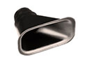 2005 Toyota MR2 Spyder Air Duct
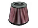 2005 Toyota MR2 Spyder Air Filter
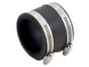 2005 Toyota MR2 Spyder Air Intake Coupling
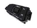 2005 Toyota MR2 Spyder Cruise Control Switch
 2005 Toyota MR2 Spyder Fuel Filter
 2005 Toyota MR2 Spyder Fuel Pressure Regulator
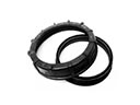 2005 Toyota MR2 Spyder Fuel Pump Seal
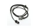 2005 Toyota MR2 Spyder Fuel Pump Wiring Harness
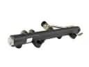 2005 Toyota MR2 Spyder Fuel Rail
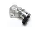 2005 Toyota MR2 Spyder Idle Control Valve
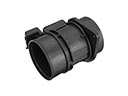 2005 Toyota MR2 Spyder Mass Air Flow Sensor
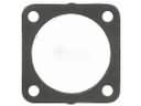 2005 Toyota MR2 Spyder Throttle Body Gasket