×
ToyotaParts- Hello
- Login or Register
- Quick Links
- Live Chat
- Track Order
- Parts Availability
- RMA
- Help Center
- Contact Us
- Shop for
- Toyota Parts
- Scion Parts
My Garage
My Account
Cart
OEM 2005 Toyota MR2 Spyder Starter Motor
Starter Ignition- Select Vehicle by Model
- Select Vehicle by VIN
Select Vehicle by Model
orMake
Model
Year
Select Vehicle by VIN
For the most accurate results, select vehicle by your VIN (Vehicle Identification Number).
1 Starter Motor found

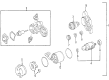 Product Specifications
- Other Name: Reman Starter Assembly; Starter Motor
- Replaces: 28100-22060
- Item Weight: 9.30 Pounds
- Item Dimensions: 10.3 x 7.1 x 5.1 inches
- Condition: New
- SKU: 28100-22060-84
- Warranty: This genuine part is guaranteed by Toyota's factory warranty.
2005 Toyota MR2 Spyder Starter Motor
Looking for affordable OEM 2005 Toyota MR2 Spyder Starter Motor? Explore our comprehensive catalogue of genuine 2005 Toyota MR2 Spyder Starter Motor. All our parts are covered by the manufacturer's warranty. Plus, our straightforward return policy and speedy delivery service ensure an unparalleled shopping experience. We look forward to your visit!
2005 Toyota MR2 Spyder Starter Motor Parts Q&A
- Q: How to service and repair the starter motor on 2005 Toyota MR2 Spyder?A: The first step for servicing the starter motor involves field frame with armature removal from the magnetic switch assembly through disconnecting the lead wire from the magnetic switch terminal while removing the 2 through bolts to pull out the assembly. First remove the field frame O-ring followed by its 2 screws and end cover and also remove the field frame O-ring. Start by using a screwdriver to maintain spring tank position and remove bushings from brush holder before taking out the brush holder. The magnetic switch assembly requires detachment of the 2 bolts to remove the starter housing (1), idler gear (2), bearing (3), clutch assembly (4), and return spring (5). You should utilize a magnetic finger tool to eliminate the steel ball from inside the clutch shaft. An ohmmeter should be used to check open circuits and ground continuity in the armature coil during inspection while verifying segment continuity between commutator regions and the absence of electrical contact between the coil core and commutator. Use a dial gauge to measure the commutator runout while using vernier calipers to check its diameter before inspecting its cleanliness against manufacturing specifications. The inspection checks both undercut depth and field coil lock and ground continuity. Use a pull scale to check the brush spring load before you replace any needed components when measuring brush length. The magnetic switch examination should include an open circuit inspection for pull-in and hold-in coils while the clutch and gear require examination for wear or damage and brush holder needs insulation continuity inspection. Resistive measurements of the bearing should be performed and new bearings installed when needed. You can use Special Service Tool: 09286-46011 together with Special Service Tool: 09820-00031 to extract the bearing for which you replace with new front and rear bearing components. The magnetic switch terminal kit requires a specific replacement process which includes removing the 3 bolts and end cover and plunger as well as gasket before measuring the contact plate wear and performing a replacement if necessary. Apply Special Service Tool: 09810-38140 to loosen terminal nuts before removing the kit parts and installing temporary terminal 30 and terminal C pieces in their proper orientation. Use a wooden block to compress the contact plate while torquing the terminal nuts to specified specifications. Afterwards clean terminal surfaces before reinstalling the magnetic switch end cover. Lubricate bearings and gears with high-temperature grease before installing the armature to the magnetic switch assembly while inserting the steel ball into the clutch shaft hole followed by correct torque installation of the starter housing, clutch assembly, and gears. The field frame gets installed with a new O-ring before the brush holder receives placement on the frame and brushes get connected and end cover installation requires a new O-ring secured by screws and through bolts. Conclude the starter installation by connecting the lead wire to terminal C followed by setting a new dust protector.
Related 2005 Toyota MR2 Spyder Parts
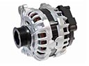 2005 Toyota MR2 Spyder Alternator
 2005 Toyota MR2 Spyder Alternator Brush
 2005 Toyota MR2 Spyder Alternator Pulley
 2005 Toyota MR2 Spyder Armature
 2005 Toyota MR2 Spyder Battery Terminal
 2005 Toyota MR2 Spyder Battery Tray
 2005 Toyota MR2 Spyder Car Batteries
 2005 Toyota MR2 Spyder Starter Brush
 2005 Toyota MR2 Spyder Starter Drive Gear
 2005 Toyota MR2 Spyder Starter Solenoid
 2005 Toyota MR2 Spyder Voltage Regulator