×
ToyotaParts- Hello
- Login or Register
- Quick Links
- Live Chat
- Track Order
- Parts Availability
- RMA
- Help Center
- Contact Us
- Shop for
- Toyota Parts
- Scion Parts
My Garage
My Account
Cart
OEM 2005 Toyota MR2 Spyder Speed Sensor
Speed Control Sensor- Select Vehicle by Model
- Select Vehicle by VIN
Select Vehicle by Model
orMake
Model
Year
Select Vehicle by VIN
For the most accurate results, select vehicle by your VIN (Vehicle Identification Number).
4 Speed Sensors found


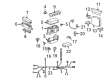
2005 Toyota MR2 Spyder Sensor
Part Number: 89413-17010$145.34 MSRP: $205.74You Save: $60.40 (30%)Ships in 1-2 Business DaysProduct Specifications- Other Name: Sensor, Transmission; Sensor, Transmission Revolution
- Part Name Code: 89413B
- Item Weight: 0.60 Pounds
- Item Dimensions: 4.5 x 2.4 x 1.7 inches
- Condition: New
- Fitment Type: Direct Replacement
- SKU: 89413-17010
- Warranty: This genuine part is guaranteed by Toyota's factory warranty.

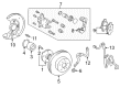
2005 Toyota MR2 Spyder Sensor Ring, Front
Part Number: 89544-52010$209.57 MSRP: $257.02You Save: $47.45 (19%)Ships in 1-3 Business DaysProduct Specifications- Other Name: Sensor, Skid Control; ABS Wheel Speed Sensor, Front, Front Left, Front Right; ABS Tone Ring; ABS Sensor; Front Speed Sensor; ABS Rotor
- Manufacturer Note: KOYO
- Position: Front
- Part Name Code: 89544
- Item Weight: 0.80 Pounds
- Item Dimensions: 9.8 x 6.5 x 1.7 inches
- Condition: New
- Fitment Type: Direct Replacement
- Require Quantity: 2
- SKU: 89544-52010
- Warranty: This genuine part is guaranteed by Toyota's factory warranty.

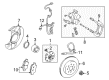
2005 Toyota MR2 Spyder Speed Sensor, Rear Driver Side
Part Number: 89546-17030$283.20 MSRP: $404.35You Save: $121.15 (30%)Ships in 1-3 Business DaysProduct Specifications- Other Name: Sensor, Speed, Rear Left-Hand; ABS Wheel Speed Sensor, Rear Left; ABS Sensor; Rear Speed Sensor; Sensor, Speed, Rear Driver Side
- Position: Rear Driver Side
- Part Name Code: 89546
- Item Weight: 0.90 Pounds
- Item Dimensions: 10.4 x 6.5 x 2.2 inches
- Condition: New
- Fitment Type: Direct Replacement
- SKU: 89546-17030
- Warranty: This genuine part is guaranteed by Toyota's factory warranty.
2005 Toyota MR2 Spyder Speed Sensor, Rear Passenger Side
Part Number: 89545-17030$264.21 MSRP: $377.23You Save: $113.02 (30%)Ships in 1-3 Business DaysProduct Specifications- Other Name: Sensor, Speed, Rear Right-Hand; ABS Wheel Speed Sensor, Rear Right; ABS Sensor; Rear Speed Sensor; Sensor, Speed, Rear Passenger Side
- Position: Rear Passenger Side
- Part Name Code: 89545
- Item Weight: 0.90 Pounds
- Item Dimensions: 10.3 x 6.5 x 2.2 inches
- Condition: New
- Fitment Type: Direct Replacement
- SKU: 89545-17030
- Warranty: This genuine part is guaranteed by Toyota's factory warranty.
2005 Toyota MR2 Spyder Speed Sensor
Looking for affordable OEM 2005 Toyota MR2 Spyder Speed Sensor? Explore our comprehensive catalogue of genuine 2005 Toyota MR2 Spyder Speed Sensor. All our parts are covered by the manufacturer's warranty. Plus, our straightforward return policy and speedy delivery service ensure an unparalleled shopping experience. We look forward to your visit!
2005 Toyota MR2 Spyder Speed Sensor Parts Q&A
- Q: How to replace the rear speed sensor on 2005 Toyota MR2 Spyder?A: A customer should begin the rear speed sensor replacement process by disconnecting the speed sensor connector followed by removing the rear wheel. The grommet and clip must be removed first before proceeding to take off the two clamp bolts and bolt and speed sensor. A proper installation of the sensor demands that both the sensor and the knuckle area be clean and that the sensor remains parallel to the knuckle surface throughout bolt tightening. The new speed sensor must use a folded bolt tightened to 8.0 Nm (82 kgf-cm, 71 inch lbs.) before using clamp bolts with 19 Nm (195 kgf-cm, 14 ft. lbs.) body side torque and 5.0 Nm (51 kgf-cm, 44 inch lbs.) upper arm side torque. Before attachment place the grommet along with the clip then secure the rear wheel by screwing it with 103 Nm (1,050 kgf-cm, 76 ft. lbs.). After connecting the speed sensor connector you must inspect the speed sensor signal.
Related 2005 Toyota MR2 Spyder Parts
 2005 Toyota MR2 Spyder Backing Plate
 2005 Toyota MR2 Spyder Brake Caliper
 2005 Toyota MR2 Spyder Brake Caliper Bracket
 2005 Toyota MR2 Spyder Brake Disc
 2005 Toyota MR2 Spyder Brake Line
 2005 Toyota MR2 Spyder Brake Pad Set
 2005 Toyota MR2 Spyder Hydraulic Hose
 2005 Toyota MR2 Spyder Spindle Nut
 2005 Toyota MR2 Spyder Wheel Bearing
 2005 Toyota MR2 Spyder Wheel Cylinder Repair Kit
 2005 Toyota MR2 Spyder Wheel Hub
 2005 Toyota MR2 Spyder Wheel Stud