×
ToyotaParts- Hello
- Login or Register
- Quick Links
- Live Chat
- Track Order
- Parts Availability
- RMA
- Help Center
- Contact Us
- Shop for
- Toyota Parts
- Scion Parts
My Garage
My Account
Cart
OEM 2004 Toyota Tacoma Rack And Pinion
Steering Rack And Pinion- Select Vehicle by Model
- Select Vehicle by VIN
Select Vehicle by Model
orMake
Model
Year
Select Vehicle by VIN
For the most accurate results, select vehicle by your VIN (Vehicle Identification Number).
5 Rack And Pinions found


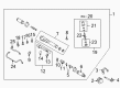
2004 Toyota Tacoma Steering Gear
Part Number: 44250-35042$547.17 MSRP: $801.89You Save: $254.72 (32%)Ships in 1-3 Business DaysProduct Specifications- Other Name: Gear Assembly, Power Steering; Rack and Pinion Assembly; Steering Gearbox; Gear Assembly; Gear Assembly, Power Steering(For Rack & Pinion)
- Replaces: 44250-35041, 44250-35040
- Part Name Code: 44250
- Item Weight: 28.30 Pounds
- Item Dimensions: 39.5 x 7.4 x 10.6 inches
- Condition: New
- Fitment Type: Direct Replacement
- SKU: 44250-35042
- Warranty: This genuine part is guaranteed by Toyota's factory warranty.

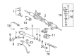
2004 Toyota Tacoma Rack, Front
Part Number: 44204-35050$404.84 MSRP: $593.30You Save: $188.46 (32%)Ships in 1-3 Business DaysProduct Specifications- Other Name: Rack Sub-Assembly, Power; Rack And Pinion Rack Gear, Front; Steering Gearbox; Steering Rack; Rack Sub-Assembly, Power Steering
- Position: Front
- Part Name Code: 44204
- Item Weight: 5.50 Pounds
- Item Dimensions: 32.1 x 3.2 x 2.8 inches
- Condition: New
- Fitment Type: Direct Replacement
- SKU: 44204-35050
- Warranty: This genuine part is guaranteed by Toyota's factory warranty.
 Product Specifications
- Other Name: Rack Sub-Assembly, Power; Rack And Pinion Rack Gear, Front; Steering Gearbox; Steering Rack; Rack Sub-Assembly, Power Steering
- Position: Front
- Part Name Code: 44204
- Item Weight: 5.60 Pounds
- Item Dimensions: 32.4 x 3.2 x 2.7 inches
- Condition: New
- Fitment Type: Direct Replacement
- SKU: 44204-35020
- Warranty: This genuine part is guaranteed by Toyota's factory warranty.

 Product Specifications
- Other Name: Reman Rack And Pinion; Rack and Pinion Assembly; Steering Gearbox; Gear Assembly
- Condition: New
- SKU: 44250-04011-84
- Warranty: This genuine part is guaranteed by Toyota's factory warranty.
 Product Specifications
- Other Name: Rack Sub-Assembly, Power; Rack And Pinion Rack Gear, Front; Steering Gearbox; Steering Rack; Rack Sub-Assembly, Power Steering
- Position: Front
- Part Name Code: 44204
- Item Weight: 5.80 Pounds
- Item Dimensions: 33.6 x 3.1 x 2.7 inches
- Condition: New
- Fitment Type: Direct Replacement
- SKU: 44204-04010
- Warranty: This genuine part is guaranteed by Toyota's factory warranty.
2004 Toyota Tacoma Rack And Pinion
Looking for affordable OEM 2004 Toyota Tacoma Rack And Pinion? Explore our comprehensive catalogue of genuine 2004 Toyota Tacoma Rack And Pinion. All our parts are covered by the manufacturer's warranty. Plus, our straightforward return policy and speedy delivery service ensure an unparalleled shopping experience. We look forward to your visit!
2004 Toyota Tacoma Rack And Pinion Parts Q&A
- Q: How to properly disassemble and reassemble a Rack and Pinion steering system on 2004 Toyota Tacoma?A: Service and repairs on the rack and pinion start by removing the pressure tubes with SST 09023-38200 and then extracting the four O-rings. Secure the Rack And Pinion assembly in SST 09612-00012 vise equipment while you remove the RH and LH tie rod ends and lock nuts by marking their starting points. The technician should remove the RH and LH clips together with rack boots and clamps with caution to prevent damage to the boots. Users should replace the screwdriver with a hammer to unstake claw washers before stabilizing the rack and pinion with a spanner when removing the rack ends through SST 09922-10010 and maintaining the correct direction. Use SST 09922-10010 to remove the rack guide spring cap lock nut after you uninstall the rack housing No.2 bracket along with its grommet. Using SST 09631-10021 as an aide, remove the rack guide spring cap followed by the rack guide spring, rack guide, and rack guide seat before taking off the rack housing cap. Use SST 09616-00011 to stop control valve shaft rotation and remove the self-locking nut before detaching the dust cover and control valve housing together with its control valve assembly by marking the positions. Apply caution while pushing the control valve assembly with its oil seal through the opening while protecting the components from breaking. Press out the rack and pinion and bushing with a 19 mm socket wrench while paying attention to avoid the rack from falling from its place. For the next steps use SST 09631-10021 to remove the oil seal and cylinder end stopper. Steerers must inspect the rack for runout and wear conditions before replacing the oil seal and bearing using SST 09950-60010 (09951-00260) and SST 09950-70010 (09951-07150). SST 09527-20011 and 09612-24014 utilities can be used to replace any necessary bearings and oil seals from the bushing by following the correct installation direction. When replacing teflon rings and O-rings in the control valve assembly users must be cautious about safeguarding the grooves before putting fresh teflon rings onto the assembly. Reconstruction requires parts application of power steering fluid together with molybdenum disulfide lithium base grease followed by the use of SST 09950-60010 (09951-00250) to install the oil seal and SST 09631-20102 to install the rack and pinion. The air tightness test for the bushing and cylinder end stopper needs to be done with SST 09631-12071. After installing the control valve assembly you must carefully place it without harming the teflon rings followed by setting the oil seal that has SST 09612-22011. Use the new gasket to mount the control valve housing after bolting it down to 18 Nm while the self-locking nut requires 25 Nm torque. Put on the dust cover together with rack housing cap and apply sealant while torquing these components to 59 Nm. After staking the rack housing cap the rack guide components must be installed and SST 09631-10021 should be used to adjust the total preload. The last step involves installing the rack housing No.2 bracket with proper torques for its RH and LH claw washers and rack ends before proceeding to rack boots, clamps, and clips installation and finishing the process by installing 2 turn pressure tubes with new O-rings torqued to 12 Nm.
Related 2004 Toyota Tacoma Parts
 2004 Toyota Tacoma Steering Wheel
 2004 Toyota Tacoma Power Steering Pump
 2004 Toyota Tacoma Steering Shaft
 2004 Toyota Tacoma Power Steering Hose
 2004 Toyota Tacoma Power Steering Reservoir
 2004 Toyota Tacoma Steering Column
 2004 Toyota Tacoma Power Steering Control Valve
 2004 Toyota Tacoma Rack and Pinion Boot
 2004 Toyota Tacoma Steering Column Cover
 2004 Toyota Tacoma Steering Gear Box
 2004 Toyota Tacoma Tie Rod End
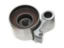 2004 Toyota Tacoma Timing Belt Idler Pulley