×
ToyotaParts- Hello
- Login or Register
- Quick Links
- Live Chat
- Track Order
- Parts Availability
- RMA
- Help Center
- Contact Us
- Shop for
- Toyota Parts
- Scion Parts
My Garage
My Account
Cart
OEM 2004 Toyota Tacoma Brake Proportioning Valve
Proportioning Valve- Select Vehicle by Model
- Select Vehicle by VIN
Select Vehicle by Model
orMake
Model
Year
Select Vehicle by VIN
For the most accurate results, select vehicle by your VIN (Vehicle Identification Number).
2 Brake Proportioning Valves found


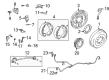
2004 Toyota Tacoma Valve Assembly, Rear
Part Number: 47910-35330$250.23 MSRP: $357.27You Save: $107.04 (30%)Ships in 1-3 Business DaysProduct Specifications- Other Name: Valve Assembly, Load Sensing With Spring; Brake Proportioning Valve, Rear; Pressure Metering Valve; Valve Assembly, Load Sensing Proportioning; Brake Proportioning Valve
- Position: Rear
- Part Name Code: 47910
- Item Weight: 1.30 Pounds
- Item Dimensions: 4.2 x 3.3 x 2.2 inches
- Condition: New
- Fitment Type: Direct Replacement
- SKU: 47910-35330
- Warranty: This genuine part is guaranteed by Toyota's factory warranty.


2004 Toyota Tacoma Valve Assembly, Rear
Part Number: 47910-35320$262.58 MSRP: $374.90You Save: $112.32 (30%)Ships in 1-3 Business DaysProduct Specifications- Other Name: Valve Assembly, Load Sensing With Spring; Brake Proportioning Valve, Rear; Pressure Metering Valve; Valve Assembly, Load Sensing Proportioning; Brake Proportioning Valve
- Position: Rear
- Part Name Code: 47910
- Item Weight: 1.90 Pounds
- Item Dimensions: 13.3 x 11.1 x 2.0 inches
- Condition: New
- Fitment Type: Direct Replacement
- SKU: 47910-35320
- Warranty: This genuine part is guaranteed by Toyota's factory warranty.
2004 Toyota Tacoma Brake Proportioning Valve
Looking for affordable OEM 2004 Toyota Tacoma Brake Proportioning Valve? Explore our comprehensive catalogue of genuine 2004 Toyota Tacoma Brake Proportioning Valve. All our parts are covered by the manufacturer's warranty. Plus, our straightforward return policy and speedy delivery service ensure an unparalleled shopping experience. We look forward to your visit!
2004 Toyota Tacoma Brake Proportioning Valve Parts Q&A
- Q: How to service and repair a Brake Proportioning Valve on 2004 Toyota Tacoma?A: To service the Load Sensing Proportioning and By-Pass Valve (LSP & BV), disconnect shackle No. 2, loose the assembly and loosen the valve bracket.Check wear parts, reassemble using correct torque requirements and attach the brake line.lastly, empty the brake line and fill the fluid pressure.
Related 2004 Toyota Tacoma Parts
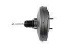 2004 Toyota Tacoma Brake Booster
 2004 Toyota Tacoma Speed Sensor
 2004 Toyota Tacoma Wheel Hub
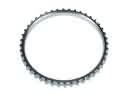 2004 Toyota Tacoma ABS Reluctor Ring
 2004 Toyota Tacoma Backing Plate
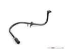 2004 Toyota Tacoma Brake Booster Vacuum Hose
 2004 Toyota Tacoma Brake Drum
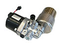 2004 Toyota Tacoma Brake Fluid Pump
 2004 Toyota Tacoma Brake Line
 2004 Toyota Tacoma Brake Shoe Set
 2004 Toyota Tacoma Wheel Cylinder
 2004 Toyota Tacoma Wheel Stud