×
ToyotaParts- Hello
- Login or Register
- Quick Links
- Live Chat
- Track Order
- Parts Availability
- RMA
- Help Center
- Contact Us
- Shop for
- Toyota Parts
- Scion Parts
My Garage
My Account
Cart
OEM 2004 Toyota Solara Heater Core
HVAC Heater Core- Select Vehicle by Model
- Select Vehicle by VIN
Select Vehicle by Model
orMake
Model
Year
Select Vehicle by VIN
For the most accurate results, select vehicle by your VIN (Vehicle Identification Number).
1 Heater Core found

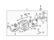
2004 Toyota Solara Heater Core
Part Number: 87107-06040$357.85 MSRP: $524.44You Save: $166.59 (32%)Ships in 1-3 Business DaysProduct Specifications- Other Name: Unit Sub-Assembly, Radiator; HVAC Heater Core; Unit Sub-Assembly, Heater Radiator
- Part Name Code: 87107A
- Item Weight: 1.60 Pounds
- Item Dimensions: 13.9 x 12.0 x 8.8 inches
- Condition: New
- Fitment Type: Direct Replacement
- SKU: 87107-06040
- Warranty: This genuine part is guaranteed by Toyota's factory warranty.
2004 Toyota Solara Heater Core
Looking for affordable OEM 2004 Toyota Solara Heater Core? Explore our comprehensive catalogue of genuine 2004 Toyota Solara Heater Core. All our parts are covered by the manufacturer's warranty. Plus, our straightforward return policy and speedy delivery service ensure an unparalleled shopping experience. We look forward to your visit!
2004 Toyota Solara Heater Core Parts Q&A
- Q: How to Service and Repair the Heater Core on 2004 Toyota Solara?A: The first step for heater core maintenance involves disconnecting the air conditioning radiator assembly through draining hose removal and connector disconnection followed by unthreading the two nuts. You must separate the mode damper servo sub-assembly by removing its three screws. First remove the heater radiator unit sub-assembly through plate unwiring and unclipping the 2 fitting claws before taking off the piping clamp. A drain pan and cloth should be ready before proceeding to catch leaking cooling water. Disassemble the airmix damper servo sub-assembly following the removal of three screws. The air conditioning tube assembly needs careful packing removal before using a 4 mm hexagon wrench to loosen and remove its two hexagon bolts. Remove the assembly by taking off the two O-rings. You need to disconnect the cooler expansion valve attached to the cooler evaporator sub-assembly No.1 before unscrewing the 2 fitting claws leading to the removal of the evaporator temperature sensor (cooler thermistor No.1). You need to remove the cooler evaporator sub-assembly No.1 where you first unscrew the 12 screws from the heater case LH before taking it out from the heater case RH while removing the 2 O-rings. Installation of the cooler evaporator sub-assembly No.1 requires the application of compressor oil (ND-OIL 8 or equivalent) to both new O-rings together with the cooler expansion valve fitting surface before the assembly steps. After that step position the cooler expansion valve to the cooler evaporator No.1. When installing the air conditioning tube assembly, apply compressor oil to the 2 new O-rings and fitting surface then mount the O-rings before securing the assembly with 2 hexagon bolts using a 4 mm hexagon wrench set to achieve 3.5 Nm torque. The installation of new packing should be done to maintain seamless fitment. Before finishing install the air conditioning radiator assembly using 2 nuts which should get tightened at 1.5 Nm after which reconnect the connector and install the drain hose. The lower position of defroster nozzle assembly needs to be installed correctly with all pins in place. The blower assembly needs 2 screws and 2 nuts with tightness set at 1.5 Nm while the connection of connectors depends on the vehicle model. Place the instrument panel reinforcement assembly by using 7 bolts and securing it with 3 caps while tightening to 20 Nm along with screwing 3 earth wires through 3 nuts. Fasten the steering column assembly by applying 21 Nm torque to 3 bolts and 2 nuts and attach both wire harness clamp and 3 connectors. Begin by installing the instrument panel junction block with three nuts set to 8.4 Nm then continue with the instrument panel brace sub-assembly No. 2 using two nuts and one bolt together with the amplifier antenna assembly by applying a nut and clamp. Insert the instrument finish panel retainer lower through 2 bolts then secure the instrument panel brace sub-assembly No.1 with a nut and bolt before tightening the screw to 9.8 Nm while also securing the wire harness with 2 clamps. The connector holder receives installation with a nut along with installation of the 2 earth wires through 2 bolts. Mount the cooler refrigerant suction hose No.1 after tape removal and installing it with compressor oil on new ORing followed by a piping clamp for security. Use the identical approach on the cooler refrigerant liquid pipe A for both 2AZ-FE and 3MZ-FE engines. Add engine coolant followed by refrigerant charging using Special Service Tool: 07110-58060 (07117-58060, 07117-58070, 07117-58080, 07117-58090, 07117-78050, 07117-88060, 07117-88070, 07117-88080) with a 550 ± 50g (19.39 ± 1.76 oz.) quantity. Afterward, check for engine coolant leaks for both engine types, as well as inspect for refrigerant leakage.
Related 2004 Toyota Solara Parts
 2004 Toyota Solara A/C Accumulator
 2004 Toyota Solara A/C Clutch
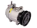 2004 Toyota Solara A/C Compressor
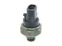 2004 Toyota Solara A/C Compressor Cut-Out Switches
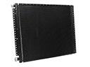 2004 Toyota Solara A/C Condenser
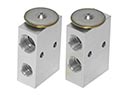 2004 Toyota Solara A/C Expansion Valve
 2004 Toyota Solara A/C Hose
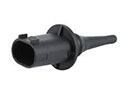 2004 Toyota Solara Ambient Temperature Sensor
 2004 Toyota Solara Blend Door Actuator
 2004 Toyota Solara Blower Motor Resistor
 2004 Toyota Solara Evaporator
 2004 Toyota Solara HVAC Pressure Switch