×
ToyotaParts- Hello
- Login or Register
- Quick Links
- Live Chat
- Track Order
- Parts Availability
- RMA
- Help Center
- Contact Us
- Shop for
- Toyota Parts
- Scion Parts
My Garage
My Account
Cart
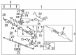
OEM 2004 Toyota Celica Rack And Pinion
Steering Rack And Pinion- Select Vehicle by Model
- Select Vehicle by VIN
Select Vehicle by Model
orMake
Model
Year
Select Vehicle by VIN
For the most accurate results, select vehicle by your VIN (Vehicle Identification Number).
1 Rack And Pinion found

 Product Specifications
- Other Name: Link Assembly, Power Steering; Rack and Pinion Assembly; Steering Gearbox; Gear Assembly; Gear Assembly, Power Steering(For Rack & Pinion)
- Replaces: 44200-20880, 44200-29025
- Part Name Code: 44250
- Item Weight: 22.10 Pounds
- Item Dimensions: 50.7 x 10.5 x 6.7 inches
- Condition: New
- Fitment Type: Direct Replacement
- SKU: 44200-20881
- Warranty: This genuine part is guaranteed by Toyota's factory warranty.
2004 Toyota Celica Rack And Pinion
Looking for affordable OEM 2004 Toyota Celica Rack And Pinion? Explore our comprehensive catalogue of genuine 2004 Toyota Celica Rack And Pinion. All our parts are covered by the manufacturer's warranty. Plus, our straightforward return policy and speedy delivery service ensure an unparalleled shopping experience. We look forward to your visit!
2004 Toyota Celica Rack And Pinion Parts Q&A
- Q: How to service and repair the Rack And Pinion on 2004 Toyota Celica?A: Soak up the Rack And Pinion assembly properly using Special Service Tool: 09612-00012 within a vise before you detach the 2 turn pressure tubes with Special Service Tool: 09023-38200. The rack ends and tie rod ends should be marked for identification before the lock nuts become loose for tie rod removal. Use needle nose pliers to gently loosen wires around the clips before you remove the wires and clip attachments from the rack boots without causing damage to them. Use a chisel and hammer to unstake the claw washers from the rack while holding the rack and pinion component with a spanner to remove the rack ends using Special Service Tool: 09922-10010 and remove the claw washers. Begin by removing the rack guide spring cap together with the conical spring washer and rack guide sub-assembly after which take out the rack housing cap and O-ring. The removal process starts by removing the control valve assembly followed by extracting the cylinder end stopper through the use of snap ring pliers. To preserve the rack housing from damage press the rack and pinion along with its oil seal using Special Service Tools in this order: 09950-70010 (09951-07200) and 09950-60010 (09951-00280), 09950-70010 (09951-07360). The rack and pinion requires inspection for bearing runout, teeth wear and damage followed by bearing replacement using Special Service Tool: 09617-35020. Before rack installation you should coat the new bearing with molybdenum disulfide lithium base grease. To replace the oil seal use a screwdriver with vinyl tape to protect the seal and apply power steering fluid to the new seal lip then insert it with Special Service Tool: 09950-60010 (09951-00210, 09951-00340, 09952-06010), 09950-70010 (09951-07100). The bearing replacement should proceed only after reinstallation of oil seals according to the same procedure. Follow these steps to change the union seats together with teflon rings and O-rings but protect the grooves from damage during replacement. Reassemble the parts by coating them with power steering fluid or molybdenum disulfide lithium base grease, then install the oil seal with correct orientation before using Special Service Tool: 09631-20051 to install the rack and pinion. Install the oil seal while being attentive and drive in the cylinder end stopper using Special Service Tool: 09612-22011 before conducting an air tightness test through Special Service Tool: 09631-12071. Put the control valve assembly first then attach the rack housing cap along with its new O-ring before torqueing it to 74 Nm (750 kgf-cm, 54 ft. lbs.). Fitting the rack guide sub-assembly requires installation of the conical spring washer and rack guide spring cap along with thread application of sealant. Prepare the total rack preload by putting rack ends temporarily in position and tightening the rack guide spring cap to 25 Nm (250 kgf-cm, 18 ft lbs.) before releasing it to 12 degrees. Special Service Tool: 09616-00011 helps to operate the control valve shaft before loosening the rack guide spring cap until the spring loses its tension. Tighten the cap to create a preload of 0.9 - 1.3 Nm (9 - 13 kgf-cm, 8.0 - 11.5 inch lbs.) while staking the cap in two opposite positions. Using Special Service Tool: 09922-10010 torque the rack ends to 62 Nm (630 kgf-cm, 46 ft. lbs.) while inserting new claw washers before installation of the rack boots and wires and clips. Verify no damage happens. Reinstall the 2 turn pressure tubes after torquing them to 23 Nm (230 kgf-cm, 17 ft. lbs.) using Special Service Tool: 09023-38200.
Related 2004 Toyota Celica Parts
 2004 Toyota Celica Steering Wheel
 2004 Toyota Celica Ignition Switch
 2004 Toyota Celica Power Steering Pump
 2004 Toyota Celica Power Steering Hose
 2004 Toyota Celica Drag Link
 2004 Toyota Celica Power Steering Reservoir
 2004 Toyota Celica Rack and Pinion Boot
 2004 Toyota Celica Steering Column
 2004 Toyota Celica Steering Gear Box
 2004 Toyota Celica Steering Shaft
 2004 Toyota Celica Tie Rod End
 2004 Toyota Celica Wiper Switch