×
ToyotaParts- Hello
- Login or Register
- Quick Links
- Live Chat
- Track Order
- Parts Availability
- RMA
- Help Center
- Contact Us
- Shop for
- Toyota Parts
- Scion Parts
My Garage
My Account
Cart
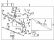
OEM 2005 Toyota Celica Rack And Pinion
Steering Rack And Pinion- Select Vehicle by Model
- Select Vehicle by VIN
Select Vehicle by Model
orMake
Model
Year
Select Vehicle by VIN
For the most accurate results, select vehicle by your VIN (Vehicle Identification Number).
1 Rack And Pinion found

 Product Specifications
- Other Name: Link Assembly, Power Steering; Rack and Pinion Assembly; Steering Gearbox; Gear Assembly; Gear Assembly, Power Steering(For Rack & Pinion)
- Replaces: 44200-20880, 44200-29025
- Part Name Code: 44250
- Item Weight: 22.10 Pounds
- Item Dimensions: 50.7 x 10.5 x 6.7 inches
- Condition: New
- Fitment Type: Direct Replacement
- SKU: 44200-20881
- Warranty: This genuine part is guaranteed by Toyota's factory warranty.
2005 Toyota Celica Rack And Pinion
Looking for affordable OEM 2005 Toyota Celica Rack And Pinion? Explore our comprehensive catalogue of genuine 2005 Toyota Celica Rack And Pinion. All our parts are covered by the manufacturer's warranty. Plus, our straightforward return policy and speedy delivery service ensure an unparalleled shopping experience. We look forward to your visit!
2005 Toyota Celica Rack And Pinion Parts Q&A
- Q: How to disassemble and assemble the Rack And Pinion on 2005 Toyota Celica?A: The vise installation of the PS rack and pinion assembly requires SST 09612-00012 while avoiding excessive tightening of the clamp. Begin by using SST 09023-38200 to remove the pressure tubes that rotate two times and then unlatch the lock nuts from the tie rod ends with matching points on both sides before proceeding with the second side. Use needle nose pliers to loosen wires and remove RH and LH clips and wires from the rack boots to each component while marking the RH and LH rack boots. Lay the claw washer flat with a chisel and hammer to unstake it while holding the rack and pinion with a spanner until removing the rack end using SST 09922-10010 in the correct direction shown in the illustration and repeat this process for the other side. Start by removing in sequence the rack guide spring cap together with its conical spring washer and rack guide sub-assembly then proceed with rack housing cap and O-ring separation. Use proper technique when you pull out the control valve assembly while maintaining the oil seal lip intact and complete the cylinder end stopper removal by utilizing snap ring pliers. The rack and pinion and oil seal removal process requires SST 09950-70010 (09951-07200) for rack and pinion press out then immediately using SST 09950-60010 (09951-00280) and SST 09950-70010 (09951-07360) to press out the oil seal while maintaining the rack housing security. Use a dial indicator to measure runout of the rack and pinion and inspect its teeth wear and damage with a maximum limit of 0.1 mm (0.004 inch) while also checking the back surface for wear and damage. You need to replace the bearing using SST 09617-35020 to extract the bearing guide nut and bearing followed by bearing lubrication with molybdenum disulfide lithium base grease and bearing installation and bearing guide nut torque to 40 Nm (410 kgf-cm, 30 ft. lbs.). To replace the oil seal sanitize a screwdriver using vinyl tape then remove the oil seal followed by lubricating the new oil seal lip with power steering fluid and pushing it into place through SST 09950-60010 (09951-00210, 09951-00340, 09952-06010) or SST 09950-70010 (09951-07100) with proper orientation. Perform replacement as needed. The replacement of the oil seal requires multiple procedures with SST 09612-20010 followed by a lubrication of the new oil seal lip using power steering fluid before insertion with SST 09950-60010 (09951-00240, 09951-00350, 09952-06010), 09950-70010 (09951-07150). To replace the bearing you should use a punch along with a hammer to tap it out then coat a new bearing with grease and install it using a brass bar and hammer. You must clean the rack housing before installation when replacing the 2 union seats through screw extractor removal followed by light tapping of new parts. Installation requires the following method to replace the teflon ring and O-ring: use a screwdriver to remove them followed by power steering fluid coating of the new O-ring, expanding the new teflon ring before coating it with fluid then installing both components with precision. The technician should replace 4 teflon rings from the control valve assembly and must expand new rings with power steering fluid before installation while using SST 09631-20081 to slide them into position. Install the rack housing oil seal lip which must be coated with power steering fluid by using SST 09950-60010 (09951-00240, 09951-00400, 09952-06010) and 09950-70010 (09951-07360) while ensuring proper orientation. Users must place the rack and pinion into position using SST 09631-20051 then coat it with power steering fluid before removing SST from the unit. Put in the oil seal to the rack housing after ensuring right positioning while staying level to prevent deformation or damage to the oil seal lip. The cylinder end stopper installation requires SST 09612-22011 and the procedure demands a new snap ring application through the use of snap ring pliers. Test the air tightness by applying a vacuum of 53 kPa (400 mm Hg, 15.75 inch Hg) for 30 seconds and monitor any vacuum variation. The control valve assembly installation should proceed without harming teflon rings or oil seal lip surfaces. After coating a new O-ring with power steering fluid, install it into the rack housing cap before cap installation followed by torquing to 74 Nm (750 kgf-cm, 54 ft. lbs.). Install the rack guide sub-assembly and conical spring washer, applying sealant to the rack guide spring cap threads, temporarily installing it, and adjusting total preload by temporarily installing the RH and LH rack ends, torquing the rack guide spring cap to 25 Nm (250 kgf-cm, 18 ft. lbs.), returning it 12°, turning the control valve shaft, loosening the cap until the spring is not functioning, and tightening it to achieve a preload of 0.9 - 1.3 Nm (9 - 13 kgf-cm, 8.0 - 11.5 inch lbs.), staking the cap in two opposing positions, and rechecking the preload. The installation of RH and LH claw washers and rack ends requires rack and pinion grooves alignment followed by rack end torquing to 62 Nm (630 kgf-cm, 46 ft. lbs.) with SST 09922-10010 and washing stake application and counter repetition for the opposite side. After installing the RH and LH rack boots and wires with clips the technician must ensure the rack and pinion hole remains free from grease obstruction and they should bend the wire to protect the boot from damage. Tie rod ends and lock nuts should be fitted next with the matchmarks properly aligned before toe-in adjustment followed by nut torque to 74 Nm (750 kgf-cm, 54 ft. lbs.). SST 09023-38200 must be used to install the 2 turn pressure tubes and torquing them to 23 Nm (230 kgf-cm, 17 ft. lbs.) through a torque wrench with 300 mm (11.81 inch) fulcrum length.
Related 2005 Toyota Celica Parts
 2005 Toyota Celica Steering Wheel
 2005 Toyota Celica Ignition Switch
 2005 Toyota Celica Power Steering Pump
 2005 Toyota Celica Power Steering Hose
 2005 Toyota Celica Drag Link
 2005 Toyota Celica Power Steering Reservoir
 2005 Toyota Celica Rack and Pinion Boot
 2005 Toyota Celica Steering Column
 2005 Toyota Celica Steering Gear Box
 2005 Toyota Celica Steering Shaft
 2005 Toyota Celica Tie Rod End
 2005 Toyota Celica Wiper Switch