×
ToyotaParts- Hello
- Login or Register
- Quick Links
- Live Chat
- Track Order
- Parts Availability
- RMA
- Help Center
- Contact Us
- Shop for
- Toyota Parts
- Scion Parts
My Garage
My Account
Cart
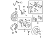
OEM 2004 Toyota Camry Parking Brake Cable
Emergency Parking Brake Release Cable- Select Vehicle by Model
- Select Vehicle by VIN
Select Vehicle by Model
orMake
Model
Year
Select Vehicle by VIN
For the most accurate results, select vehicle by your VIN (Vehicle Identification Number).
4 Parking Brake Cables found

2004 Toyota Camry Front Cable
Part Number: 46410-06030$44.44 MSRP: $61.85You Save: $17.41 (29%)Ships in 1-3 Business DaysProduct Specifications- Other Name: Cable Assembly, Parking; Brake Cable; Cable Assembly, Parking Brake
- Replaces: 46410-33130
- Part Name Code: 46410
- Item Weight: 2.00 Pounds
- Item Dimensions: 16.0 x 12.2 x 3.0 inches
- Condition: New
- Fitment Type: Direct Replacement
- SKU: 46410-06030
- Warranty: This genuine part is guaranteed by Toyota's factory warranty.

2004 Toyota Camry Front Cable
Part Number: 46410-33120$81.87 MSRP: $114.92You Save: $33.05 (29%)Ships in 1-3 Business DaysProduct Specifications- Other Name: Cable Assembly, Parking; Brake Cable; Cable Assembly, Parking Brake
- Part Name Code: 46410
- Item Weight: 2.00 Pounds
- Item Dimensions: 16.0 x 12.2 x 3.0 inches
- Condition: New
- Fitment Type: Direct Replacement
- SKU: 46410-33120
- Warranty: This genuine part is guaranteed by Toyota's factory warranty.

2004 Toyota Camry Cable Assembly, Parking Brake
Part Number: 46430-33100$88.15 MSRP: $123.73You Save: $35.58 (29%)Ships in 1-3 Business DaysProduct Specifications- Other Name: Cable Assembly, Parking; Parking Brake Cable; Brake Cable
- Manufacturer Note: W(VSC)
- Part Name Code: 46430
- Item Weight: 2.40 Pounds
- Item Dimensions: 17.8 x 13.2 x 3.3 inches
- Condition: New
- Fitment Type: Direct Replacement
- SKU: 46430-33100
- Warranty: This genuine part is guaranteed by Toyota's factory warranty.

2004 Toyota Camry Cable Assembly, Parking Brake
Part Number: 46420-33100$81.63 MSRP: $114.58You Save: $32.95 (29%)Ships in 1-3 Business DaysProduct Specifications- Other Name: Cable Assembly, Parking; Parking Brake Cable; Brake Cable
- Manufacturer Note: W(VSC)
- Part Name Code: 46420
- Item Weight: 2.70 Pounds
- Item Dimensions: 18.2 x 12.8 x 3.1 inches
- Condition: New
- Fitment Type: Direct Replacement
- SKU: 46420-33100
- Warranty: This genuine part is guaranteed by Toyota's factory warranty.
2004 Toyota Camry Parking Brake Cable
Looking for affordable OEM 2004 Toyota Camry Parking Brake Cable? Explore our comprehensive catalogue of genuine 2004 Toyota Camry Parking Brake Cable. All our parts are covered by the manufacturer's warranty. Plus, our straightforward return policy and speedy delivery service ensure an unparalleled shopping experience. We look forward to your visit!
2004 Toyota Camry Parking Brake Cable Parts Q&A
- Q: How to replace the Floor Shift Parking Brake Cable Assembly on 2004 Toyota Camry?A: The process to replace the Floor Shift Parking Lock Cable Assembly begins with disconnecting the battery negative terminal followed by the removal of steering wheel covers along with the horn button assembly and steering wheel assembly using Special Service Tool: 09950-50013 (09951-05010, 09952-05010, 09953-05020, 09954-05021). Next, remove the instrument cluster finish panel, steering column cover, front door scuff plate LH, cowl side trim sub-assembly LH, instrument panel coin box sub-assembly, instrument panel sub-assembly upper, instrument panel insert sub-assembly lower LH, console panel upper rear, console box carpet, rear console box, instrument panel cup holder tray (without ashtray), and instrument panel ash receptacle assembly (with ashtray), followed by the console panel upper, console box front, air duct rear No.2, air duct rear No.1, and console box duct No.1. First disconnect the parking lock cable end from the lever pin of the floor shift assembly and then disconnect the floor shift cable from the assembly and clamp with a screwdriver before removing the cable from its bracket by detaching its clamp while positioning the ignition switch to ACC or ON. Installing the new cable starts with connecting it to the upper bracket and cable clamp followed by sliding the cap through the hole and setting the accessory tool correctly based on vehicle production at either TMC or TMMK. The operation for inserting the lever pin into the floor shift parking lock cable's hole requires the release of the automatic adjustment part's lock key claw before locking the key and removing the accessory tool. After checking the key interlock operation, reinstall the console box duct No.1, air ducts, console box front, console panel upper, cup holder tray, ash receptacle assembly, rear console box, console box carpet, console panel upper rear, instrument panel insert sub-assembly lower LH, instrument panel sub-assembly upper, instrument panel coin box sub-assembly, cowl side trim sub-assembly LH, front door scuff plate LH, steering column cover, instrument cluster finish panel, steering wheel assembly, horn button assembly, and steering wheel covers in reverse order. The SRS warning light assessment requires finishing the process by reattaching the negative battery terminal.
Related 2004 Toyota Camry Parts
 2004 Toyota Camry Wheel Bearing
 2004 Toyota Camry Wheel Hub
 2004 Toyota Camry Wheel Stud
 2004 Toyota Camry Brake Pad Set
 2004 Toyota Camry Backing Plate
 2004 Toyota Camry Brake Caliper Bracket
 2004 Toyota Camry Brake Disc
 2004 Toyota Camry Brake Shoe Set
 2004 Toyota Camry Hydraulic Hose
 2004 Toyota Camry Parking Brake Shoe
 2004 Toyota Camry Wheel Cylinder
 2004 Toyota Camry Wheel Cylinder Repair Kit