×
ToyotaParts- Hello
- Login or Register
- Quick Links
- Live Chat
- Track Order
- Parts Availability
- RMA
- Help Center
- Contact Us
- Shop for
- Toyota Parts
- Scion Parts
My Garage
My Account
Cart
OEM 2004 Scion xB Rack And Pinion
Steering Rack And Pinion- Select Vehicle by Model
- Select Vehicle by VIN
Select Vehicle by Model
orMake
Model
Year
Select Vehicle by VIN
For the most accurate results, select vehicle by your VIN (Vehicle Identification Number).
1 Rack And Pinion found

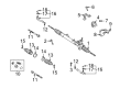
2004 Scion xB Steering Gear
Part Number: 44200-52340$610.09 MSRP: $894.08You Save: $283.99 (32%)Ships in 1-3 Business DaysProduct Specifications- Other Name: Rack and Pinion Assembly; Steering Gearbox; Gear Assembly; Steering Gear Assembly; Link Assembly, Power Steering
- Part Name Code: 44200
- Item Weight: 13.70 Pounds
- Item Dimensions: 50.2 x 10.4 x 6.6 inches
- Condition: New
- Fitment Type: Direct Replacement
- SKU: 44200-52340
- Warranty: This genuine part is guaranteed by Toyota's factory warranty.
2004 Scion xB Rack And Pinion
Looking for affordable OEM 2004 Scion xB Rack And Pinion? Explore our comprehensive catalogue of genuine 2004 Scion xB Rack And Pinion. All our parts are covered by the manufacturer's warranty. Plus, our straightforward return policy and speedy delivery service ensure an unparalleled shopping experience. We look forward to your visit!
2004 Scion xB Rack And Pinion Parts Q&A
- Q: How to Overhaul the Rack and Pinion in Power Steering Systems on 2004 Scion xB?A: The start of power steering link assy replacement requires applying either power steering fluid or molybdenum disulfide lithium base grease to specific components. The service requires removal of fr wiper arm RH, fr wiper arm LH, hood to cowl top seal, cowl top ventilator louver RH, cowl top ventilator louver LH, windshield wiper motor & link assy and cowl panel sub-assy. Start examination of the center front wheel then remove the steering column hole cover plate. Fix the steering wheel inside a seat belt to secure its position and mark the sliding yoke sub-assy and intermediate shaft to split them apart. Loosen the bolt. The technician detaches clip A from the steering column hole cover sub-assy NO.1 while taking care to avoid damaging clip B. Then the hood sub-assy removal occurs along with draining power steering fluid and front wheels extraction. The tie rod end sub-assy LH (Special Service Tool: 09620-62011) and tie rod end sub-assy RH need separation before the engine under cover LH and RH removal procedure can begin. To disconnect the pressure feed tube assy use the instrument Special Service Tool 09023-12700 alongside hose removal through the removal of clip and return hose. Fasten the 2 NO.1 engine hangers (Parts NO.: NO.1 engine hanger: 12281-21010, Bolt: 91642-81025, Torque: 40 Nm) under the engine assembly after separating the front suspension arm sub-assy lower NO.1 LH (Special Service Tool: 09620-00011) and RH from each other. NO.1 engine hanger: 12281-21010, Bolt: 91642-81025, Torque: 40 Nm). The technician must remove the front suspension crossmember sub-assy and power steering rack housing heat insulator and steering column hole cover sub-assy NO.1. Steer away from the steering intermediate shaft by first taping the steering link assy and intermediate shaft before removing the power steering rack and pinion which entails marking the steering link assy and bracket NO.2 along with all bolts and nuts followed by bracket NO.2 and grommet NO.2 and steering link assy removal while keeping the bolt torqued with the nut secured. Completely remove both the steering right turn pressure tube together with the steering left turn pressure tube using Special Service Tool 09023-38200. The power steering rack and pinion installation requires Special Service Tool: 09612-00012 and demands vinyl tape coverage around its structure. First detach the tie rod end sub-assy LH and RH before removing the steering rack boot clips and boot NO.2 clamp while preventing any boot damage. Use Special Service Tool: 09922-10010 to remove the steering rack end sub-assy after separating its components by removing steering rack boot NO.2 and NO.1. The service technician should start by removing the rack guide alongside the power steering control valve and cylinder end stopper. Use Special Service Tool: 09950-70010 (09951-07200) and a press to uninstall the power steering rack and pinion before proceeding to remove its power steering rack bush along with the oil seal. When removing the rack steering piston ring isolate it from the grooves during the process. Check the power steering rack and pinion for a maximum runout of 0.1 mm while inspecting both the teeth and damage as well as the runout. Also inspect tie rod end sub-assy LH and RH for appropriate torque levels. Installation of the power steering rack housing oil seal must be done correctly before adding the rack steering piston ring with power steering fluid adjustments where required.
Related 2004 Scion xB Parts
 2004 Scion xB Power Steering Pump
 2004 Scion xB Steering Wheel
 2004 Scion xB Dimmer Switch
 2004 Scion xB Drag Link
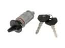 2004 Scion xB Ignition Lock Assembly
 2004 Scion xB Power Steering Hose
 2004 Scion xB Power Steering Reservoir
 2004 Scion xB Rack and Pinion Boot
 2004 Scion xB Steering Column
 2004 Scion xB Steering Column Cover
 2004 Scion xB Steering Shaft
 2004 Scion xB Tie Rod End