×
ToyotaParts- Hello
- Login or Register
- Quick Links
- Live Chat
- Track Order
- Parts Availability
- RMA
- Help Center
- Contact Us
- Shop for
- Toyota Parts
- Scion Parts
My Garage
My Account
Cart
OEM 2003 Toyota Tundra Wheel Hub
Wheel Axle Hub- Select Vehicle by Model
- Select Vehicle by VIN
Select Vehicle by Model
orMake
Model
Year
Select Vehicle by VIN
For the most accurate results, select vehicle by your VIN (Vehicle Identification Number).
2 Wheel Hubs found


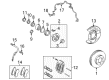
2003 Toyota Tundra Hub Assembly, Front
Part Number: 43502-35110$242.31 MSRP: $345.96You Save: $103.65 (30%)Ships in 1 Business DayProduct Specifications- Other Name: Hub Sub-Assembly, Front Axle; Wheel Hub, Front; Wheel Hub Repair Kit; Front Hub; Hub; Hub Sub-Assembly, Front Axle, Passenger Side; Hub Sub-Assembly, Front Axle, Driver Side; Wheel Hub
- Position: Front
- Replaces: 43502-04050, 43502-0C010
- Item Weight: 9.70 Pounds
- Item Dimensions: 8.1 x 8.3 x 8.2 inches
- Condition: New
- Fitment Type: Direct Replacement
- SKU: 43502-35110
- Warranty: This genuine part is guaranteed by Toyota's factory warranty.


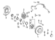
2003 Toyota Tundra Hub Assembly, Front
Part Number: 43502-35170$224.37 MSRP: $320.34You Save: $95.97 (30%)Ships in 1-2 Business DaysProduct Specifications- Other Name: Hub Sub-Assembly, Front Axle; Wheel Hub, Front; Wheel Hub Repair Kit; Front Hub; Hub Sub-Assembly, Front Axle, Passenger Side; Hub Sub-Assembly, Front Axle, Driver Side; Wheel Hub
- Position: Front
- Replaces: 43502-04040
- Item Weight: 8.20 Pounds
- Item Dimensions: 6.9 x 6.5 x 4.8 inches
- Condition: New
- Fitment Type: Direct Replacement
- SKU: 43502-35170
- Warranty: This genuine part is guaranteed by Toyota's factory warranty.
2003 Toyota Tundra Wheel Hub
Looking for affordable OEM 2003 Toyota Tundra Wheel Hub? Explore our comprehensive catalogue of genuine 2003 Toyota Tundra Wheel Hub. All our parts are covered by the manufacturer's warranty. Plus, our straightforward return policy and speedy delivery service ensure an unparalleled shopping experience. We look forward to your visit!
2003 Toyota Tundra Wheel Hub Parts Q&A
- Q: How to service and repair the wheel hub on 2003 Toyota Tundra?A: Start hub wheel service by first using screwdriver and hammer to remove the front wheel alongside its grease cap. The drive shaft disconnection process for 4WD models includes removing the cotter pin and lock cap prior to taking out the lock nut while holding the brakes engaged. Operators must disconnect both ABS speed sensor and wire harness clamp from the steering knuckle through the removal of two bolts. First disconnect the brake caliper along with disc by removing the steel bolt and brake tube clamp from the steering knuckle before removing the two brake caliper and disc bolts while ensuring to not damage the brake tubular and securely supporting the caliper. Start by taking off the shock absorber before proceeding to disconnect the lower ball joint through removal of the 4 essential bolts. Before extracting the steering knuckle engineers should remove its cotter pin and nut before disconnecting it using Special Service Tool: 09950-40011 (09951-04010, 09952-04010, 09553-04020, 09554-04010, 09955-04031, 09958-04011). Installation requires similar steps in reverse order. First secure the drive shaft within the axle hub while loosely tightening the nut to maintain the oil seal condition before linking the steering knuckle to the upper suspension arm then fasten the new cotter pin and further tighten it up to 60 degrees if the pin holes are not aligned, and apply torque of 105 Nm (1,100 kgf-cm, 77 ft. lbs.). Connect the steering knuckle to its lower ball joint with four bolts that need 80 Nm of torque (820 kgf-cm or 59 ft. lbs.). After that, install the shock absorber. To install the brake caliper, first place the disc and caliper before securing the two bolts with 123 Nm (1,250 kgf-cm, 90 ft. lbs.) torque. The brake line clamp should be attached to the steering knuckle through a 28 Nm (285 kgf-cm, 21 ft. lbs.) torqued bolt. The ABS speed sensor and wire harness clamp must be connected to the steering knuckle using 2 bolts that should be tightened to 8.0 Nm (82 kgf-cm, 71 ft. lbs.). The drive shaft lock nut installation requires braking of the vehicle while the torque reaches 235 Nm (2,400 kgf-cm, 173 ft. lbs.) followed by cap installation along with a new cotter pin that should be tightened up to 60° if possible. To complete the task, first install the grease cap before torquing the front wheel to 110 Nm (1,150 kgf-cm, 83 ft. lbs.) and depress the brake pedal multiple times and inspect the front wheel alignment and ensure the ABS speed sensor signal is intact.
Related 2003 Toyota Tundra Parts
 2003 Toyota Tundra Wheel Bearing
 2003 Toyota Tundra Brake Caliper
 2003 Toyota Tundra Backing Plate
 2003 Toyota Tundra Speed Sensor
 2003 Toyota Tundra Brake Disc
 2003 Toyota Tundra Brake Line
 2003 Toyota Tundra Brake Pad Set
 2003 Toyota Tundra Brake Shoe Set
 2003 Toyota Tundra Hydraulic Hose
 2003 Toyota Tundra Spindle Nut
 2003 Toyota Tundra Wheel Bearing Dust Cap
 2003 Toyota Tundra Wheel Cylinder Repair Kit