×
ToyotaParts- Hello
- Login or Register
- Quick Links
- Live Chat
- Track Order
- Parts Availability
- RMA
- Help Center
- Contact Us
- Shop for
- Toyota Parts
- Scion Parts
My Garage
My Account
Cart
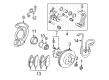
OEM 2003 Toyota Sienna Brake Caliper
Caliper- Select Vehicle by Model
- Select Vehicle by VIN
Select Vehicle by Model
orMake
Model
Year
Select Vehicle by VIN
For the most accurate results, select vehicle by your VIN (Vehicle Identification Number).
2 Brake Calipers found

 Product Specifications
- Other Name: Cylinder Assembly, Disc; Disc Brake Caliper, Front Right; Cylinder Assembly, Front Disc Brake, Passenger Side; Brake Caliper
- Position: Passenger Side
- Part Name Code: 47730
- Item Weight: 12.10 Pounds
- Item Dimensions: 10.2 x 7.7 x 5.5 inches
- Condition: New
- Fitment Type: Direct Replacement
- SKU: 47730-08020
- Warranty: This genuine part is guaranteed by Toyota's factory warranty.
- Product Specifications
- Other Name: Cylinder Assembly, Disc; Disc Brake Caliper, Front Left; Cylinder Assembly, Disc Brake, Driver Side; Brake Caliper
- Position: Driver Side
- Part Name Code: 47750
- Item Weight: 12.20 Pounds
- Item Dimensions: 10.1 x 7.8 x 5.3 inches
- Condition: New
- Fitment Type: Direct Replacement
- SKU: 47750-08020
- Warranty: This genuine part is guaranteed by Toyota's factory warranty.
2003 Toyota Sienna Brake Caliper
Looking for affordable OEM 2003 Toyota Sienna Brake Caliper? Explore our comprehensive catalogue of genuine 2003 Toyota Sienna Brake Caliper. All our parts are covered by the manufacturer's warranty. Plus, our straightforward return policy and speedy delivery service ensure an unparalleled shopping experience. We look forward to your visit!
2003 Toyota Sienna Brake Caliper Parts Q&A
- Q: How to service and repair the brake caliper on 2003 Toyota Sienna?A: To change the brake caliper, the front wheel should be removed and the disc fixed. Unscrew the flexible hose, collect draining fluid and remove the caliper by loosening installation bolts. Remove the shims and brake pads. To install, reverse the procedure, fill back brake fluid, bleed the system and look after leakages.
Related 2003 Toyota Sienna Parts
 2003 Toyota Sienna Speed Sensor
 2003 Toyota Sienna Wheel Hub
 2003 Toyota Sienna Brake Caliper Bracket
 2003 Toyota Sienna Brake Caliper Piston
 2003 Toyota Sienna Brake Disc
 2003 Toyota Sienna Brake Drum
 2003 Toyota Sienna Brake Shoe Set
 2003 Toyota Sienna Hydraulic Hose
 2003 Toyota Sienna Parking Brake Shoe
 2003 Toyota Sienna Spindle Nut
 2003 Toyota Sienna Wheel Cylinder
 2003 Toyota Sienna Wheel Stud