×
ToyotaParts- Hello
- Login or Register
- Quick Links
- Live Chat
- Track Order
- Parts Availability
- RMA
- Help Center
- Contact Us
- Shop for
- Toyota Parts
- Scion Parts
My Garage
My Account
Cart
OEM 2003 Toyota Corolla Alternator
Generator- Select Vehicle by Model
- Select Vehicle by VIN
Select Vehicle by Model
orMake
Model
Year
Select Vehicle by VIN
For the most accurate results, select vehicle by your VIN (Vehicle Identification Number).
2 Alternators found


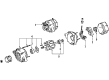
2003 Toyota Corolla Alternator
Part Number: 27060-0D110-84$195.42 MSRP: $237.30You Save: $41.88 (18%)Ships in 1-3 Business DaysProduct Specifications- Other Name: Reman Alternator 1Zz
- Replaces: 27060-0D110
- Item Weight: 12.80 Pounds
- Item Dimensions: 9.3 x 7.2 x 8.2 inches
- Condition: New
- SKU: 27060-0D110-84
- Warranty: This genuine part is guaranteed by Toyota's factory warranty.

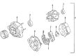
2003 Toyota Corolla Alternator
Part Number: 27060-22040-84$155.11 MSRP: $204.17You Save: $49.06 (25%)Ships in 1-3 Business DaysProduct Specifications- Other Name: Alternator Assembly, With Regulator
- Replaces: 27060-22040
- Item Weight: 12.90 Pounds
- Item Dimensions: 9.3 x 7.3 x 8.4 inches
- Condition: New
- SKU: 27060-22040-84
- Warranty: This genuine part is guaranteed by Toyota's factory warranty.
2003 Toyota Corolla Alternator
Looking for affordable OEM 2003 Toyota Corolla Alternator? Explore our comprehensive catalogue of genuine 2003 Toyota Corolla Alternator. All our parts are covered by the manufacturer's warranty. Plus, our straightforward return policy and speedy delivery service ensure an unparalleled shopping experience. We look forward to your visit!
2003 Toyota Corolla Alternator Parts Q&A
- Q: How to service and repair the alternator on 2003 Toyota Corolla?A: Start the alternator servicing procedure by disconnecting the engine under cover RH and the fan and generator V belt. The alternator requires disposal of the generator assembly by first discharging the wire clamp from the rectifier end frame wire clip then removing the rubber cap together with the nut before removing both the alternator wire and connector. The two alternator securing bolts should be removed as the last step. When installing the 12 mm head bolts tighten them to 25 Nm (250 kgf.cm, 18 ft.lbf) and the 14 mm head bolts require a torque of 54 Nm (550 kgf.cm, 39 ft.lbf).
Related 2003 Toyota Corolla Parts
 2003 Toyota Corolla Starter Motor
 2003 Toyota Corolla Battery Terminal
 2003 Toyota Corolla Starter Solenoid
 2003 Toyota Corolla Voltage Regulator
 2003 Toyota Corolla Alternator Bearing
 2003 Toyota Corolla Alternator Brush
 2003 Toyota Corolla Alternator Case Kit
 2003 Toyota Corolla Alternator Pulley
 2003 Toyota Corolla Armature
 2003 Toyota Corolla Battery Cable
 2003 Toyota Corolla Battery Tray
 2003 Toyota Corolla Starter Drive Gear