×
ToyotaParts- Hello
- Login or Register
- Quick Links
- Live Chat
- Track Order
- Parts Availability
- RMA
- Help Center
- Contact Us
- Shop for
- Toyota Parts
- Scion Parts
My Garage
My Account
Cart
OEM 2003 Toyota Avalon Wheel Hub
Wheel Axle Hub- Select Vehicle by Model
- Select Vehicle by VIN
Select Vehicle by Model
orMake
Model
Year
Select Vehicle by VIN
For the most accurate results, select vehicle by your VIN (Vehicle Identification Number).
3 Wheel Hubs found


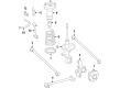
2003 Toyota Avalon Hub & Bearing Assembly, Rear Axle, Passenger Side
Part Number: 42450-33020$401.67 MSRP: $588.65You Save: $186.98 (32%)Ships in 1-3 Business DaysProduct Specifications- Other Name: Hub&Bearing Assembly, Rear Axle, Driver Side; Wheel Hub Repair Kit; Axle Bearing
- Manufacturer Note: W(ABS)
- Position: Rear
- Replaces: 42450-07010, 42450-06010
- Item Weight: 7.90 Pounds
- Item Dimensions: 7.1 x 6.9 x 5.1 inches
- Condition: New
- Fitment Type: Direct Replacement
- SKU: 42450-33020
- Warranty: This genuine part is guaranteed by Toyota's factory warranty.

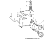
2003 Toyota Avalon Hub Assembly
Part Number: 42410-33040$415.97 MSRP: $609.60You Save: $193.63 (32%)Ships in 1-3 Business DaysProduct Specifications- Other Name: Hub&Bearing Assembly; Rear Wheel Bearing & Hub; Wheel Hub Repair Kit; Axle Bearing; Hub & Bearing; Rear Axle Assembly, Passenger & Driver Side; Wheel Bearing and Hub Assembly.
- Replaces: 42410-07010, 42410-06020
- Item Weight: 7.70 Pounds
- Item Dimensions: 6.6 x 4.7 x 6.5 inches
- Condition: New
- Fitment Type: Direct Replacement
- SKU: 42410-33040
- Warranty: This genuine part is guaranteed by Toyota's factory warranty.


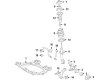
2003 Toyota Avalon Hub Sub-Assembly, Front Axle, Passenger Side
Part Number: 43502-06040$162.49 MSRP: $230.03You Save: $67.54 (30%)Product Specifications- Other Name: Hub Sub-Assembly, Front Axle; Hub Sub-Assembly, Front Axle, Driver Side; Wheel Hub Repair Kit; Wheel Hub
- Position: Front
- Replaces: 43502-33030, 43502-33010, 43502-06020
- Item Weight: 5.00 Pounds
- Item Dimensions: 6.7 x 6.7 x 4.8 inches
- Condition: New
- Fitment Type: Direct Replacement
- SKU: 43502-06040
- Warranty: This genuine part is guaranteed by Toyota's factory warranty.
2003 Toyota Avalon Wheel Hub
Looking for affordable OEM 2003 Toyota Avalon Wheel Hub? Explore our comprehensive catalogue of genuine 2003 Toyota Avalon Wheel Hub. All our parts are covered by the manufacturer's warranty. Plus, our straightforward return policy and speedy delivery service ensure an unparalleled shopping experience. We look forward to your visit!
2003 Toyota Avalon Wheel Hub Parts Q&A
- Q: How to service and repair the wheel hub on 2003 Toyota Avalon?A: The process for wheel hub maintenance begins with taking off the front wheel while tightening its bolts to 103 Nm (1,050 kgf-cm, 76 ft. lbs.). First measure the bearing backlash and axle hub deviation by detaching the 2 bolts, brake caliper and disc while maintaining a tight grip on the brake caliper. A dial indicator should measure backlash at the center point of the axle hub near the center with an allowable limit of 0.05 mm (0.0020 inch). If the measurement exceeds this threshold, replace the bearing. It is crucial to check the deviation at the axle hub surface beyond the hub bolt using a maximum 0.05 mm (0.0020 inch) limit; if the limit is exceeded the axle hub needs replacement. Securely reattach the disc with brake caliper along with reinstalling two bolts while applying 107 Nm (1,090 kgf-cm, 79 ft. lbs.) torque strength. The drive shaft lock nut needs removal through the steps of first dislodging the cotter pin along with the lock cap followed by brake application to loosen the nut with 294 Nm (3,000 kgf-cm, 217 ft. lbs.) torque. Take out disc and brake caliper a second time followed by securely supporting the brake caliper while removing its 2 bolts. Begin the ABS speed sensor wire disconnection process by unscrewing the bolt with torques set at 8.0 Nm (82 kgf-cm, 71 inch lbs.). Before securing it in place during assembly, apply engine oil to the threads of the nuts at the bottom shock absorber side while using 211 Nm of torque (2,150 kgf-cm, 156 ft. lbs.). Possible through the use of SS Tool 09610-20012 and by removing its nut which requires a 49 Nm torque force (500 kgf-cm, 36 ft. lbs.) while also removing the cotter pin. The lower ball joint requires removal from the lower suspension arm when disconnected following torque procedures at 127 Nm (1,300 kgf-cm, 94 ft. lbs.) for all 2 nuts and the bolt. The process for steering knuckle and axle hub removal involves two nut and bolt fasteners located below the shock absorber that should be unscrewed while safeguarding the boot and ABS speed sensor rotor. Installation proceeds through the reverse sequence of removal before checking both ABS speed sensor signals and measuring front wheel alignment. The installation of VSC requires performing a steering angle sensor zero point calibration procedure following system installation.
Related 2003 Toyota Avalon Parts
 2003 Toyota Avalon Wheel Bearing
 2003 Toyota Avalon Brake Caliper
 2003 Toyota Avalon Speed Sensor
 2003 Toyota Avalon Backing Plate
 2003 Toyota Avalon Brake Booster Vacuum Hose
 2003 Toyota Avalon Brake Caliper Bracket
 2003 Toyota Avalon Brake Caliper Piston
 2003 Toyota Avalon Brake Pad Set
 2003 Toyota Avalon Hydraulic Hose
 2003 Toyota Avalon Spindle Nut
 2003 Toyota Avalon Wheel Cylinder
 2003 Toyota Avalon Yaw Sensor