×
ToyotaParts- Hello
- Login or Register
- Quick Links
- Live Chat
- Track Order
- Parts Availability
- RMA
- Help Center
- Contact Us
- Shop for
- Toyota Parts
- Scion Parts
My Garage
My Account
Cart
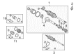
OEM 2003 Toyota Avalon Axle Shaft
Car Axle Shaft- Select Vehicle by Model
- Select Vehicle by VIN
Select Vehicle by Model
orMake
Model
Year
Select Vehicle by VIN
For the most accurate results, select vehicle by your VIN (Vehicle Identification Number).
2 Axle Shafts found


2003 Toyota Avalon Axle Assembly, Driver Side
Part Number: 43420-08010$404.50 MSRP: $592.80You Save: $188.30 (32%)Ships in 1-3 Business DaysProduct Specifications- Other Name: Shaft Assembly, Front Drive; CV Axle Assembly, Front Left; GSP Cv Axle; Axle Shaft; Shaft Assembly, Front Drive, Driver Side; CV Axle Assembly
- Position: Driver Side
- Part Name Code: 43420
- Item Weight: 23.00 Pounds
- Item Dimensions: 31.0 x 5.1 x 5.3 inches
- Condition: New
- Fitment Type: Direct Replacement
- SKU: 43420-08010
- Warranty: This genuine part is guaranteed by Toyota's factory warranty.
- Product Specifications
- Other Name: Shaft Assembly, Front Drive; CV Axle Assembly, Front Right; GSP Cv Axle; Axle Shaft; Shaft Assembly, Front Drive, Passenger Side; CV Axle Assembly
- Position: Passenger Side
- Replaces: 43410-06430
- Part Name Code: 43410
- Item Weight: 20.80 Pounds
- Item Dimensions: 44.1 x 5.7 x 5.5 inches
- Condition: New
- Fitment Type: Direct Replacement
- SKU: 43410-07031
- Warranty: This genuine part is guaranteed by Toyota's factory warranty.
2003 Toyota Avalon Axle Shaft
Looking for affordable OEM 2003 Toyota Avalon Axle Shaft? Explore our comprehensive catalogue of genuine 2003 Toyota Avalon Axle Shaft. All our parts are covered by the manufacturer's warranty. Plus, our straightforward return policy and speedy delivery service ensure an unparalleled shopping experience. We look forward to your visit!
2003 Toyota Avalon Axle Shaft Parts Q&A
- Q: How to remove and install the axle shaft on 2003 Toyota Avalon?A: Before handling the axle shaft installation and removal process start by supporting the hub bearing with Special Service Tool: 09608-16042 (09608-02021, 09608-02041) in case the vehicle weight needs to be placed on it. It is important during drive shaft removal to protect the ABS speed sensor rotor serration by preventing damage to it. The first task involves removing the front vehicle wheel using a 103 Nm torque followed by extracting the front fender apron seal and emptying the ATF before proceeding to release the drive shaft lock nut after clearing its lock cap and using 294 Nm torque for nut removal when brake pressure is applied. The service requires using a plastic hammer to disconnect the tie rod end from the steering knuckle and lower suspension arm from the lower ballpoint and drive shaft from the axle hub while taking precautions to not harm the boot and ABS speed sensor rotor. For LH drive shaft hub nut removal use a combination of a hub nut wrench and hammer handle or similar equipment while protecting dust cover and oil seal from damage. The installation process requires gear oil coating of the inboard joint shaft along with the differential case sliding surface and a downward orientation of the snap ring opening side and sound or feel verification for pinion shaft contact and validation of axial travel between 2-3 mm (0.08-0.12 inch) before confirming the drive shaft remains immobile by hand. The RH drive shaft requires premise removal of its bearing lock bolt at 32 Nm (330 kgf-cm, 24 ft. lbs.) torque before snap ring and drive shaft extraction with pliers while continuing to safeguard the dust cover and oil seal. Reinstall the components in the opposite direction of removal and verify the front wheel alignment if equipped with VSC then check the ABS speed sensor signal after completing the installation.
Related 2003 Toyota Avalon Parts
 2003 Toyota Avalon Control Arm
 2003 Toyota Avalon Bump Stop
 2003 Toyota Avalon CV Boot
 2003 Toyota Avalon CV Joint
 2003 Toyota Avalon Coil Spring Insulator
 2003 Toyota Avalon Coil Springs
 2003 Toyota Avalon Lateral Link
 2003 Toyota Avalon Shock And Strut Mount
 2003 Toyota Avalon Shock and Strut Boot
 2003 Toyota Avalon Strut Housing
 2003 Toyota Avalon Sway Bar Bracket
 2003 Toyota Avalon Transfer Case Output Shaft Snap Ring