×
ToyotaParts- Hello
- Login or Register
- Quick Links
- Live Chat
- Track Order
- Parts Availability
- RMA
- Help Center
- Contact Us
- Shop for
- Toyota Parts
- Scion Parts
My Garage
My Account
Cart
OEM 2002 Toyota Avalon Axle Shaft
Car Axle Shaft- Select Vehicle by Model
- Select Vehicle by VIN
Select Vehicle by Model
orMake
Model
Year
Select Vehicle by VIN
For the most accurate results, select vehicle by your VIN (Vehicle Identification Number).
2 Axle Shafts found


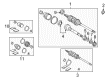
2002 Toyota Avalon Axle Assembly, Driver Side
Part Number: 43420-08010$404.50 MSRP: $592.80You Save: $188.30 (32%)Ships in 1-3 Business DaysProduct Specifications- Other Name: Shaft Assembly, Front Drive; CV Axle Assembly, Front Left; GSP Cv Axle; Axle Shaft; Shaft Assembly, Front Drive, Driver Side; CV Axle Assembly
- Position: Driver Side
- Part Name Code: 43420
- Item Weight: 23.00 Pounds
- Item Dimensions: 31.0 x 5.1 x 5.3 inches
- Condition: New
- Fitment Type: Direct Replacement
- SKU: 43420-08010
- Warranty: This genuine part is guaranteed by Toyota's factory warranty.
- Product Specifications
- Other Name: Shaft Assembly, Front Drive; CV Axle Assembly, Front Right; GSP Cv Axle; Axle Shaft; Shaft Assembly, Front Drive, Passenger Side; CV Axle Assembly
- Position: Passenger Side
- Replaces: 43410-06430
- Part Name Code: 43410
- Item Weight: 20.80 Pounds
- Item Dimensions: 44.1 x 5.7 x 5.5 inches
- Condition: New
- Fitment Type: Direct Replacement
- SKU: 43410-07031
- Warranty: This genuine part is guaranteed by Toyota's factory warranty.
2002 Toyota Avalon Axle Shaft
Looking for affordable OEM 2002 Toyota Avalon Axle Shaft? Explore our comprehensive catalogue of genuine 2002 Toyota Avalon Axle Shaft. All our parts are covered by the manufacturer's warranty. Plus, our straightforward return policy and speedy delivery service ensure an unparalleled shopping experience. We look forward to your visit!
2002 Toyota Avalon Axle Shaft Parts Q&A
- Q: How to remove and install the axle shaft on 2002 Toyota Avalon?A: Start the axle shaft removal process by supporting the hub bearing with Special Service Tool: 09608-16042 and overlapping tools 09608-02021 and 09608-02041 when the vehicle weight rests on them. Disconnection of the drive shaft from the axle hub requires extreme caution because it could damage the ABS speed sensor rotor serration. Start by tightening the front wheel to 103 Nm (1,050 kgf-cm, 76 ft. lbs.) then proceed to remove the front fender apron seal while draining the ATF from the system. The installation process starts with unlocking the drive shaft lock nut through its cotter pin followed by lock cap removal. The technician must apply brake pressure prior to nut removal at 294 Nm (3,000 kgf-cm, 217 ft. lbs.). The process starts with using a plastic hammer to disconnect three components: the tie rod end from the steering knuckle and the lower suspension arm from the lower ball joint along with the drive shaft from the axle hub while guarding against any boot or ABS speed sensor rotor damage. To remove the LH drive shaft's hub nut use a hub nut wrench alongside a hammer handle or equivalent tools while maintaining the dust cover and oil seal from damage. For drive shaft installation apply gear oil to both the inboard joint shaft and differential case sliding surface followed by downward orientation of the snap ring opening component while testing pinion shaft touch by sound then inspecting stated axial movement amount between 2-3mm (0.08-0.12 inches) and confirming manual resistance against drive shaft removal. The RH drive shaft requires removal of the bearing lock bolt at 32 Nm torque (330 kgf-cm, 24 ft. lbs.) followed by snap ring and drive shaft extraction with pliers yet maintaining caution to avoid harming the dust cover and oil seal. The reversing steps for installation should be followed together with ABS speed sensor signal and front wheel alignment checks after installing the components. The zero point calibration of the steering angle sensor must be performed in vehicles that have VSC.
Related 2002 Toyota Avalon Parts
 2002 Toyota Avalon Control Arm
 2002 Toyota Avalon Bump Stop
 2002 Toyota Avalon CV Boot
 2002 Toyota Avalon CV Joint
 2002 Toyota Avalon Coil Spring Insulator
 2002 Toyota Avalon Coil Springs
 2002 Toyota Avalon Lateral Link
 2002 Toyota Avalon Shock And Strut Mount
 2002 Toyota Avalon Shock and Strut Boot
 2002 Toyota Avalon Strut Housing
 2002 Toyota Avalon Sway Bar Bracket
 2002 Toyota Avalon Transfer Case Output Shaft Snap Ring