×
ToyotaParts- Hello
- Login or Register
- Quick Links
- Live Chat
- Track Order
- Parts Availability
- RMA
- Help Center
- Contact Us
- Shop for
- Toyota Parts
- Scion Parts
My Garage
My Account
Cart
OEM 2002 Toyota Land Cruiser Brake Caliper
Caliper- Select Vehicle by Model
- Select Vehicle by VIN
Select Vehicle by Model
orMake
Model
Year
Select Vehicle by VIN
For the most accurate results, select vehicle by your VIN (Vehicle Identification Number).
4 Brake Calipers found


2002 Toyota Land Cruiser Caliper, Rear Driver Side
Part Number: 47750-60101$176.24 MSRP: $249.49You Save: $73.25 (30%)Ships in 1-2 Business DaysProduct Specifications- Other Name: Cylinder Assembly, Disc; Disc Brake Caliper, Rear Left; Cylinder Assembly, Disc Brake, Rear Driver Side; Brake Caliper
- Position: Rear Driver Side
- Replaces: 47750-60100
- Part Name Code: 47750A
- Item Weight: 8.70 Pounds
- Condition: New
- Fitment Type: Direct Replacement
- SKU: 47750-60101
- Warranty: This genuine part is guaranteed by Toyota's factory warranty.


2002 Toyota Land Cruiser Caliper, Passenger Side
Part Number: 47730-60101$176.24 MSRP: $249.49You Save: $73.25 (30%)Ships in 1-2 Business DaysProduct Specifications- Other Name: Cylinder Assembly, Disc; Disc Brake Caliper, Rear Right; Cylinder Assembly, Rear Disc Brake, Passenger Side; Brake Caliper
- Position: Passenger Side
- Replaces: 47730-60100
- Part Name Code: 47730B
- Item Weight: 8.80 Pounds
- Item Dimensions: 10.3 x 7.4 x 7.4 inches
- Condition: New
- Fitment Type: Direct Replacement
- SKU: 47730-60101
- Warranty: This genuine part is guaranteed by Toyota's factory warranty.


2002 Toyota Land Cruiser Caliper, Driver Side
Part Number: 47750-60080$247.32 MSRP: $353.11You Save: $105.79 (30%)Ships in 1-3 Business DaysProduct Specifications- Other Name: Cylinder Assembly, Disc; Disc Brake Caliper, Front Left; Cylinder Assembly, Disc Brake, Driver Side; Brake Caliper
- Position: Driver Side
- Part Name Code: 47750
- Item Weight: 11.80 Pounds
- Item Dimensions: 10.3 x 8.0 x 5.6 inches
- Condition: New
- Fitment Type: Direct Replacement
- SKU: 47750-60080
- Warranty: This genuine part is guaranteed by Toyota's factory warranty.
2002 Toyota Land Cruiser Caliper, Passenger Side
Part Number: 47730-60080$247.32 MSRP: $353.11You Save: $105.79 (30%)Ships in 1-3 Business DaysProduct Specifications- Other Name: Cylinder Assembly, Disc; Disc Brake Caliper, Front Right; Cylinder Assembly, Front Disc Brake, Passenger Side; Brake Caliper
- Position: Passenger Side
- Part Name Code: 47730
- Item Weight: 12.20 Pounds
- Item Dimensions: 10.6 x 8.0 x 5.6 inches
- Condition: New
- Fitment Type: Direct Replacement
- SKU: 47730-60080
- Warranty: This genuine part is guaranteed by Toyota's factory warranty.
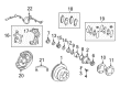
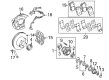
2002 Toyota Land Cruiser Brake Caliper
Looking for affordable OEM 2002 Toyota Land Cruiser Brake Caliper? Explore our comprehensive catalogue of genuine 2002 Toyota Land Cruiser Brake Caliper. All our parts are covered by the manufacturer's warranty. Plus, our straightforward return policy and speedy delivery service ensure an unparalleled shopping experience. We look forward to your visit!
2002 Toyota Land Cruiser Brake Caliper Parts Q&A
- Q: How to service and repair the brake caliper on 2002 Toyota Land Cruiser?A: Service procedures for the brake caliper start with screwdriver removal of cylinder boots followed by a piece of cloth between the piston and caliper before releasing the piston with compressed air while keeping fingers safe from the piston. Use a screwdriver to uninstall the brake cylinder piston seals and then proceed to remove the sliding pin, pin boot along with sliding bushing by applying tape to the screwdriver tip beforehand. It is crucial during assembly to put the sliding pin and sliding bushing in the lower part and the plain sliding pin in the upper part. Pad lining inspection requires a ruler to measure pad layer thickness as specified by the 12.0 mm standard (0.472 inch) and 1.0 mm minimum (0.039 inch); report pad change when thickness checks minimum specifications and show uneven wear. Measure the disc thickness using a micrometer when the disc is temporarily fastened by 3 hub nuts to check if it meets the 18.0 mm (0.709 inch) standard and the minimum of 16.0 mm (0.611 inch), do a disc replacement or grinding if needed due to scoring or uneven wear. Check the disc runout by using a dial indicator at 10 mm (0.39 inch) from the outside edge until maximum runout reaches 0.1 mm (0.0040 inch); proceed with checking bearing play and axle hub runout and adjust or grind the disc when necessary. The proper adjustment involves using the disc as described previously with the same torque specifications for hub nuts but the disc must rotate one-fifth of its previous position before runout measurement takes place after the correct tightening of hub nuts. The installation of the disc should occur in the position showing the minimum level of runout, provided that the runout measurement is below 0.1 mm (0.0040 inch); else, replace the disc for another measurement. Follow the final step by installing the torque plate. Then tighten its 2 bolts to 103 Nm (1,050 kgf-cm, 78 ft. lbs.) torque. After that reinstall the components in reverse disassembly order by oiling specific parts with lithium soap base glycol grease.
Related 2002 Toyota Land Cruiser Parts
 2002 Toyota Land Cruiser Wheel Bearing
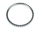 2002 Toyota Land Cruiser ABS Reluctor Ring
 2002 Toyota Land Cruiser Backing Plate
 2002 Toyota Land Cruiser Brake Caliper Bracket
 2002 Toyota Land Cruiser Brake Caliper Piston
 2002 Toyota Land Cruiser Brake Disc
 2002 Toyota Land Cruiser Brake Line
 2002 Toyota Land Cruiser Brake Pad Set
 2002 Toyota Land Cruiser Spindle Nut
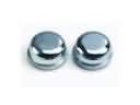 2002 Toyota Land Cruiser Wheel Bearing Dust Cap
 2002 Toyota Land Cruiser Wheel Cylinder Repair Kit
 2002 Toyota Land Cruiser Wheel Hub