×
ToyotaParts- Hello
- Login or Register
- Quick Links
- Live Chat
- Track Order
- Parts Availability
- RMA
- Help Center
- Contact Us
- Shop for
- Toyota Parts
- Scion Parts
My Garage
My Account
Cart
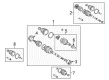
OEM 2002 Toyota Corolla Axle Shaft
Car Axle Shaft- Select Vehicle by Model
- Select Vehicle by VIN
Select Vehicle by Model
orMake
Model
Year
Select Vehicle by VIN
For the most accurate results, select vehicle by your VIN (Vehicle Identification Number).
4 Axle Shafts found

2002 Toyota Corolla Axle Assembly, Passenger Side
Part Number: 43410-02091$468.34 MSRP: $686.36You Save: $218.02 (32%)Ships in 1-3 Business DaysProduct Specifications- Other Name: Shaft Assembly, Front Drive; CV Axle Assembly, Front Right; GSP Cv Axle; Axle Shaft; Shaft Assembly, Front Drive, Passenger Side; CV Axle Assembly
- Position: Passenger Side
- Part Name Code: 43410
- Item Weight: 14.90 Pounds
- Item Dimensions: 29.8 x 7.4 x 6.4 inches
- Condition: New
- Fitment Type: Direct Replacement
- SKU: 43410-02091
- Warranty: This genuine part is guaranteed by Toyota's factory warranty.
- Product Specifications
- Other Name: Shaft Assembly, Front Drive; CV Axle Assembly, Front Left; GSP Cv Axle; Axle Shaft; Shaft Assembly, Front Drive, Driver Side; CV Axle Assembly
- Position: Driver Side
- Part Name Code: 43420
- Item Weight: 14.10 Pounds
- Item Dimensions: 29.2 x 7.5 x 6.4 inches
- Condition: New
- Fitment Type: Direct Replacement
- SKU: 43420-02091
- Warranty: This genuine part is guaranteed by Toyota's factory warranty.
- Product Specifications
- Other Name: Shaft Assembly, Front Drive; CV Axle Assembly, Front Left; GSP Cv Axle; Axle Shaft; Shaft Assembly, Front Drive, Driver Side; CV Axle Assembly
- Manufacturer Note: W(ABS)
- Position: Driver Side
- Part Name Code: 43420
- Item Weight: 15.20 Pounds
- Item Dimensions: 30.1 x 7.4 x 6.4 inches
- Condition: New
- Fitment Type: Direct Replacement
- SKU: 43420-02101
- Warranty: This genuine part is guaranteed by Toyota's factory warranty.
- Product Specifications
- Other Name: Shaft Assembly, Front Drive; CV Axle Assembly, Front Right; GSP Cv Axle; Axle Shaft; Shaft Assembly, Front Drive, Passenger Side; CV Axle Assembly
- Manufacturer Note: W(ABS)
- Position: Passenger Side
- Part Name Code: 43410
- Item Weight: 14.50 Pounds
- Item Dimensions: 29.5 x 7.3 x 6.7 inches
- Condition: New
- Fitment Type: Direct Replacement
- SKU: 43410-02101
- Warranty: This genuine part is guaranteed by Toyota's factory warranty.
2002 Toyota Corolla Axle Shaft
Looking for affordable OEM 2002 Toyota Corolla Axle Shaft? Explore our comprehensive catalogue of genuine 2002 Toyota Corolla Axle Shaft. All our parts are covered by the manufacturer's warranty. Plus, our straightforward return policy and speedy delivery service ensure an unparalleled shopping experience. We look forward to your visit!
2002 Toyota Corolla Axle Shaft Parts Q&A
- Q: How to service and repair the axle shaft on 2002 Toyota Corolla?A: You must first examine the drive shaft by checking outboard joint play while confirming inboard joint thrust movement alongside verifying both joints have no radial movement. Booth damage assessment should also be done as the first step for shaft servicing and repair. The inboard joint boot clamps can be removed by using pliers to squeeze the claws before pulling the boot toward the outboard joint. Tag and mark all components of the inboard and outboard joint shafts as well as the tripod yet refrain from using a punch. Extract the inboard joint shaft from the outboard joint shaft. Apply a snap ring expander tool to take out the snap ring before marking the joint shaft of the outboard direction and tripod section and delicately remove the tripod using a hammer and brass bar. The outboard joint boot must be taken off before cutting the dynamic damper clamp with side cutters then removing the dynamic damper. To remove the outboard joint boot you should pinch its claws to free the small clamp then cut the large clamp before removing it without breaking apart the outboard joint. Mount the outboard joint shaft in a soft jaw vise while using Special Service Tool: 09950-00020 with a press to get the inboard joint shaft dust cover then use a screwdriver and hammer to extract the No. 2 dust deflector by avoiding damage to the ABS speed sensor rotor. Use Special Service Tool: 09309-36010, 09316-20011 and a press to install a new No. 2 dust deflector after which a new dust cover can be mounted on the inboard joint shaft. First install the boots along with the dynamic damper (RH drive shaft) while sealing the outboard joint shaft spline with vinyl tape to protect it from damage. Squeeze outboard joint and boot with grease until reaching 165 to 185 g then apply 190 to 210 g of grease in the inboard joint and boot before securing the matchmarks to install the inboard joint shaft into the outboard joint shaft. The boots need to maintain their correct position without being stretched or contracted along their standard drive shaft length. The installation process requires new clamps on the inboard joint boot that should be attached through plier use of the claw mechanism. Affix the outboard joint large boot clamp to its boot using Special Service Tool: 09521-24010 before tightening it with Special Service Tool: 09240-00020 to achieve a 1.9 mm (0.075 inch) or lesser clearance. When installing the RH drive shaft damper onto the shaft groove first set it to 431.3 plus or minus 3.0 mm (16.980 plus or minus 0.118 inch). After clamping the boot properly secure it with Special Service Tool: 09521-24010 to pinch it down then adjust this clearance to 1.9 mm (0.075 inch) or less by using Special Service Tool: 09240-00020.
Related 2002 Toyota Corolla Parts
 2002 Toyota Corolla CV Joint
 2002 Toyota Corolla CV Boot
 2002 Toyota Corolla Shock Absorber
 2002 Toyota Corolla Steering Knuckle
 2002 Toyota Corolla Bump Stop
 2002 Toyota Corolla Coil Spring Insulator
 2002 Toyota Corolla Lateral Link
 2002 Toyota Corolla Rear Crossmember
 2002 Toyota Corolla Shock And Strut Mount
 2002 Toyota Corolla Suspension Strut Rod
 2002 Toyota Corolla Sway Bar Bracket
 2002 Toyota Corolla Sway Bar Kit