×
ToyotaParts- Hello
- Login or Register
- Quick Links
- Live Chat
- Track Order
- Parts Availability
- RMA
- Help Center
- Contact Us
- Shop for
- Toyota Parts
- Scion Parts
My Garage
My Account
Cart
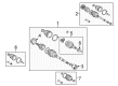
OEM 2001 Toyota Corolla Axle Shaft
Car Axle Shaft- Select Vehicle by Model
- Select Vehicle by VIN
Select Vehicle by Model
orMake
Model
Year
Select Vehicle by VIN
For the most accurate results, select vehicle by your VIN (Vehicle Identification Number).
4 Axle Shafts found

2001 Toyota Corolla Axle Assembly, Passenger Side
Part Number: 43410-02091$468.34 MSRP: $686.36You Save: $218.02 (32%)Ships in 1-3 Business DaysProduct Specifications- Other Name: Shaft Assembly, Front Drive; CV Axle Assembly, Front Right; GSP Cv Axle; Axle Shaft; Shaft Assembly, Front Drive, Passenger Side; CV Axle Assembly
- Position: Passenger Side
- Part Name Code: 43410
- Item Weight: 14.90 Pounds
- Item Dimensions: 29.8 x 7.4 x 6.4 inches
- Condition: New
- Fitment Type: Direct Replacement
- SKU: 43410-02091
- Warranty: This genuine part is guaranteed by Toyota's factory warranty.
- Product Specifications
- Other Name: Shaft Assembly, Front Drive; CV Axle Assembly, Front Left; GSP Cv Axle; Axle Shaft; Shaft Assembly, Front Drive, Driver Side; CV Axle Assembly
- Position: Driver Side
- Part Name Code: 43420
- Item Weight: 14.10 Pounds
- Item Dimensions: 29.2 x 7.5 x 6.4 inches
- Condition: New
- Fitment Type: Direct Replacement
- SKU: 43420-02091
- Warranty: This genuine part is guaranteed by Toyota's factory warranty.
- Product Specifications
- Other Name: Shaft Assembly, Front Drive; CV Axle Assembly, Front Left; GSP Cv Axle; Axle Shaft; Shaft Assembly, Front Drive, Driver Side; CV Axle Assembly
- Manufacturer Note: W(ABS)
- Position: Driver Side
- Part Name Code: 43420
- Item Weight: 15.20 Pounds
- Item Dimensions: 30.1 x 7.4 x 6.4 inches
- Condition: New
- Fitment Type: Direct Replacement
- SKU: 43420-02101
- Warranty: This genuine part is guaranteed by Toyota's factory warranty.
- Product Specifications
- Other Name: Shaft Assembly, Front Drive; CV Axle Assembly, Front Right; GSP Cv Axle; Axle Shaft; Shaft Assembly, Front Drive, Passenger Side; CV Axle Assembly
- Manufacturer Note: W(ABS)
- Position: Passenger Side
- Part Name Code: 43410
- Item Weight: 14.50 Pounds
- Item Dimensions: 29.5 x 7.3 x 6.7 inches
- Condition: New
- Fitment Type: Direct Replacement
- SKU: 43410-02101
- Warranty: This genuine part is guaranteed by Toyota's factory warranty.
2001 Toyota Corolla Axle Shaft
Looking for affordable OEM 2001 Toyota Corolla Axle Shaft? Explore our comprehensive catalogue of genuine 2001 Toyota Corolla Axle Shaft. All our parts are covered by the manufacturer's warranty. Plus, our straightforward return policy and speedy delivery service ensure an unparalleled shopping experience. We look forward to your visit!
2001 Toyota Corolla Axle Shaft Parts Q&A
- Q: How to remove and install the axle shaft on 2001 Toyota Corolla?A: The first step to remove an axle shaft requires support from Special Service Tool: 09608-16042 (09608-02021, 09608-02041) to sustain the hub bearing weight in case the vehicle weight needs to rest on it. Users must handle the ABS speed sensor rotor serration with care while performing drive shaft disconnection from the axle hub section. Start the procedure by draining gear oil from M/T or ATF from A/T and then remove the under engine covers along with the front wheels. First extract the cotter pin then remove the lock cap before using brakes to take out the nut. Special Service Tool: 09628-62011 enables disconnection of the tie rod end from the steering knuckle and the lower suspension arm requires removal of its bolt and two nuts to separate from the lower ball joint. Use a plastic hammer to disconnect the drive shaft from the axle hub by gently detaching it while avoiding any harm to the boot and ABS speed sensor rotor. To remove the LH drive shaft through the transaxle you need a hammer and hub nut wrench while maintaining dust cover and oil seal safety. The hub nut wrench is also needed for RH drive shaft removal. You should dismantle the inboard joint shaft by extracting its snap ring with a screwdriver. The installation process begins with installing a new snap ring onto the inboard joint shaft before applying gear oil to both the inboard joint shaft and differential case sliding surfaces. Install this snap ring with its opening toward the downward position. Install the drive shaft using a brass bar under constant hammer pressure while maintaining protection of the dust cover and oil seal and verifying an axial play range from 2 to 3 millimeters (0.08 to 0.12 inches) and drive shaft removal difficulty. Secure the drive shaft to the hub by a method that avoids affecting any part of the boot and ABS speed sensor rotor during installation. Use a torque wrench set to 142 Nm for the lower ball joint lower suspension arm assembly before installing the tie rod end to the steering knuckle by inserting the nut and new cotter pin while tightening the nut up to 60 degrees if required. The drive shaft lock nut should be installed under brake application at 225 Nm torque (2,300 kgf-cm, 166 ft. lbs.) before adding lock cap and new cotter pin and tightening to additional torque of 60 degrees if required. The service technician should install the engine under covers and front wheel while applying 103 Nm (1,050 kgf-cm, 76 ft. lbs.) torque; they should also verify and fill the gear oil (M/T) or ATF (A/T). The last inspection includes checking both front wheel alignment and the ABS speed sensor signal.
Related 2001 Toyota Corolla Parts
 2001 Toyota Corolla CV Joint
 2001 Toyota Corolla CV Boot
 2001 Toyota Corolla Shock Absorber
 2001 Toyota Corolla Steering Knuckle
 2001 Toyota Corolla Bump Stop
 2001 Toyota Corolla Coil Spring Insulator
 2001 Toyota Corolla Lateral Link
 2001 Toyota Corolla Rear Crossmember
 2001 Toyota Corolla Shock And Strut Mount
 2001 Toyota Corolla Suspension Strut Rod
 2001 Toyota Corolla Sway Bar Bracket
 2001 Toyota Corolla Sway Bar Kit