×
ToyotaParts- Hello
- Login or Register
- Quick Links
- Live Chat
- Track Order
- Parts Availability
- RMA
- Help Center
- Contact Us
- Shop for
- Toyota Parts
- Scion Parts
My Garage
My Account
Cart
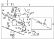
OEM 2002 Toyota Celica Rack And Pinion
Steering Rack And Pinion- Select Vehicle by Model
- Select Vehicle by VIN
Select Vehicle by Model
orMake
Model
Year
Select Vehicle by VIN
For the most accurate results, select vehicle by your VIN (Vehicle Identification Number).
2 Rack And Pinions found

 Product Specifications
- Other Name: Link Assembly, Power Steering; Rack and Pinion Assembly; Steering Gearbox; Gear Assembly; Gear Assembly, Power Steering(For Rack & Pinion)
- Replaces: 44200-20880, 44200-29025
- Part Name Code: 44250
- Item Weight: 22.10 Pounds
- Item Dimensions: 50.7 x 10.5 x 6.7 inches
- Condition: New
- Fitment Type: Direct Replacement
- SKU: 44200-20881
- Warranty: This genuine part is guaranteed by Toyota's factory warranty.
 Product Specifications
- Other Name: Rack Sub-Assembly, Power; Rack And Pinion Rack Gear, Front; Steering Gearbox; Steering Rack; Rack; Rack Sub-Assembly, Power Steering
- Position: Front
- Part Name Code: 44204
- Item Weight: 5.50 Pounds
- Item Dimensions: 32.4 x 3.1 x 2.8 inches
- Condition: New
- Fitment Type: Direct Replacement
- SKU: 44204-20400
- Warranty: This genuine part is guaranteed by Toyota's factory warranty.
2002 Toyota Celica Rack And Pinion
Looking for affordable OEM 2002 Toyota Celica Rack And Pinion? Explore our comprehensive catalogue of genuine 2002 Toyota Celica Rack And Pinion. All our parts are covered by the manufacturer's warranty. Plus, our straightforward return policy and speedy delivery service ensure an unparalleled shopping experience. We look forward to your visit!
2002 Toyota Celica Rack And Pinion Parts Q&A
- Q: How to remove and reinstall the Rack And Pinion on 2002 Toyota Celica?A: The procedure for rack and pinion removal requires front wheel alignment straight forward followed by removal of the steering wheel pad and steering wheel. Proceed by removing the RH, center, and LH engine under covers followed by RH and LH tie rod end and No. 2 intermediate shaft assembly disconnect. Disconnect the steering pressure feed and return tubes by utilizing Special Service Tool: 09023-38400 and then unfasten the tube clamp. To start the procedure disconnect the column hole cover sub-assembly while also removing the engine hood then fix the engine sling device to engine hangers by removing 4 bolts and No. 2 cylinder head cover and disconnecting PCV hoses. Install the engine hangers No. 1 and No. 2 using bolt: 91512-B1016 or 91512-61020, and torque to 38 Nm (388 kgf-cm, 28 ft. lbs.). For 1ZZ-FE Engine use hanger No. 1: 12281-22021 and No. 2: 12281-15040 or 12281-15050 while 2ZZ-FE Engine needs hanger No. 1: 12281-88600 and No. 2: 12282-88600. The ball joint needs detachment from the lower suspension arm and stabilizer bar through disassembly of the related nut. After removing bolt A and 3 nuts you should disconnect the engine rear mount insulator and front suspension member and then detach the engine front mount insulator and front suspension member through removing the two bolts (bolt B). You should use a transmission jack to support the front suspension member while removing its lower suspension arm and rack and pinion assembly with 6 bolts (C, D, and E). The rack and pinion assembly removal begins with disassembly of four bolts followed by the process of matchmarking intermediate extension and control valve shaft then removing bolt and intermediate extension. Begin by installing the engine rear mount insulator followed by the engine rear mount bracket which should be secured using 3 bolts torqued to 64 Nm and a through bolt torqued to 87 Nm. The installation process starts with aligning rack and pinion assembly matchmarks while torquing the bolt to 35 Nm (360 kgf-cm, 26 ft. lbs.) and attaching it with 4 bolts to the front suspension member torqued to 58 Nm (590 kgf-cm, 43 ft. lbs.). After installing the front suspension member along with the lower suspension arm and rack and pinion assembly use 6 bolts (C: 157 Nm (1,600 kgf-cm, 116 ft. lbs.), D: 157 Nm (1,600 kgf-cm, 116 ft. lbs.), E: 39 Nm (400 kgf-cm, 29 ft. lbs.)). Finally, join the engine front mount insulator and front suspension member with bolt B tightened to 52 Nm (530 kgf-cm, 38 ft. lbs.) while joining the engine rear mount insulator with bolt Connect the stabilizer bar by torquing its nut to 44 Nm (450 kgf-cm, 33 ft. lbs.) before re-hooking the lower ball joint to the lower suspension arm. Reinstall the 4 bolts on the No. 2 cylinder head cover then restore all PCV hoses before removing the engine sling hardware. Use Special Service Tool: 09023-38400 to connect pressure feed and return tubes by torquing them to 40 Nm (410 kgf-cm, 30 ft. lbs.). After that, install the engine hood followed by connecting the column hole cover sub-assembly and the tube clamp with bolt torque at 7.8 Nm (80 kgf-cm, 69 inch lbs.). Reinstall all engine under covers starting with the RH and moving to the center then the LH units as you connect the No. 2 intermediate shaft assembly with both RH and LH tie rod ends. Proceed with the following sequence: position the front wheels straight, place the spiral cable at the center and mount the steering wheel with mark alignment before tightening the set nut briefly then drain the power steering fluids and check the wheel center point followed by setting the nut torque to 50 Nm (510 kgf-cm, 37 ft. lbs.) and install the wheel pad while inspecting wheel alignment.
Related 2002 Toyota Celica Parts
 2002 Toyota Celica Steering Wheel
 2002 Toyota Celica Ignition Switch
 2002 Toyota Celica Power Steering Pump
 2002 Toyota Celica Power Steering Hose
 2002 Toyota Celica Drag Link
 2002 Toyota Celica Power Steering Control Valve
 2002 Toyota Celica Power Steering Reservoir
 2002 Toyota Celica Rack and Pinion Boot
 2002 Toyota Celica Steering Gear Box
 2002 Toyota Celica Steering Shaft
 2002 Toyota Celica Tie Rod End
 2002 Toyota Celica Wiper Switch