×
ToyotaParts- Hello
- Login or Register
- Quick Links
- Live Chat
- Track Order
- Parts Availability
- RMA
- Help Center
- Contact Us
- Shop for
- Toyota Parts
- Scion Parts
My Garage
My Account
Cart
OEM 2001 Toyota Tundra Ball Joint
Control Arm Joint- Select Vehicle by Model
- Select Vehicle by VIN
Select Vehicle by Model
orMake
Model
Year
Select Vehicle by VIN
For the most accurate results, select vehicle by your VIN (Vehicle Identification Number).
3 Ball Joints found


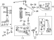
2001 Toyota Tundra Upper Ball Joint, Front
Part Number: 43310-39016$49.94 MSRP: $69.51You Save: $19.57 (29%)Ships in 1-3 Business DaysProduct Specifications- Other Name: Joint Assembly, Front Upper Ball; Suspension Ball Joint, Front Upper; Upper Ball Joints; Front Upper Ball Joint Assembly for Driver & Passenger Side.
- Position: Front Upper
- Replaces: 43310-39085, 43310-39065
- Item Weight: 1.50 Pounds
- Item Dimensions: 5.5 x 3.2 x 2.5 inches
- Condition: New
- Fitment Type: Direct Replacement
- SKU: 43310-39016
- Warranty: This genuine part is guaranteed by Toyota's factory warranty.


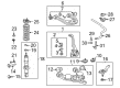
2001 Toyota Tundra Lower Ball Joint, Front Driver Side
Part Number: 43340-39356$108.65 MSRP: $152.52You Save: $43.87 (29%)Ships in 1-3 Business DaysProduct Specifications- Other Name: Joint Assembly, Lower Ball; Suspension Ball Joint, Front Left Lower; Joint Assembly, Lower Ball, Front Driver Side; Suspension Ball Joint; Ball Joint
- Position: Front Driver Side
- Replaces: 43340-39355
- Part Name Code: 43340A
- Item Weight: 4.90 Pounds
- Item Dimensions: 5.5 x 3.2 x 2.4 inches
- Condition: New
- Fitment Type: Direct Replacement
- SKU: 43340-39356
- Warranty: This genuine part is guaranteed by Toyota's factory warranty.


2001 Toyota Tundra Lower Ball Joint, Front Passenger Side
Part Number: 43330-39466$108.65 MSRP: $152.52You Save: $43.87 (29%)Ships in 1-3 Business DaysProduct Specifications- Other Name: Joint Assembly, Lower Ball; Suspension Ball Joint, Front Right Lower; Joint Assembly, Lower Ball, Front Passenger Side; Suspension Ball Joint; Ball Joint
- Position: Front Passenger Side
- Replaces: 43330-39465
- Part Name Code: 43330K
- Item Weight: 4.90 Pounds
- Item Dimensions: 5.4 x 3.3 x 2.4 inches
- Condition: New
- Fitment Type: Direct Replacement
- SKU: 43330-39466
- Warranty: This genuine part is guaranteed by Toyota's factory warranty.
2001 Toyota Tundra Ball Joint
Looking for affordable OEM 2001 Toyota Tundra Ball Joint? Explore our comprehensive catalogue of genuine 2001 Toyota Tundra Ball Joint. All our parts are covered by the manufacturer's warranty. Plus, our straightforward return policy and speedy delivery service ensure an unparalleled shopping experience. We look forward to your visit!
2001 Toyota Tundra Ball Joint Parts Q&A
- Q: How to service and repair the lower ball joint on 2001 Toyota Tundra?A: Service and repair of the lower ball joint starts with taking out the front wheel from the vehicle. Keep the 4 lower ball joint set bolts slightly loose while you detach the tie rod end by removing its cotter pin and nut before using Special Service Tool: 09610-20012 to disconnect it from the lower ball joint. The initial step involves removing the lower ball joint through the procedure of first using Special Service Tool: 09628-62011 to disconnect it from the lower suspension arm before the 4 lower ball joint set bolts can be removed. When lifting the upper suspension arm and steering knuckle you should remove the lower ball joint before securely supporting the upper suspension arm and steering knuckle. Thoroughly inspect the ball joint boot then test the joint rotation through five back-and-forth movements of the ball joint stud prior to nut installation. A torque wrench operator should use a slow and steady motion to turn the nut at a rate of 1 turn per 2 - 4 seconds until the 5th turn and set a target twisting torque between 0.1 Nm and 2.5 Nm (11kgf-cm to 25 kgf-cm or 1 inch lbs to 22 inch lbs). The installation process begins with lifting the upper suspension arm and steering knuckle for lower ball joint installation by using four bolts temporarily followed by lower ball joint fixation to lower suspension arm through set nut and new cotter pin while tightening to 140 Nm (1,450 kgf-cm, 103 ft. lbs.). You must tighten the nut until the holes of the cotter pin become aligned if they are not matching. You should connect the lower ball joint to the tie rod end through a new cotter pin along with a nut while tightening it to reach 91 Nm (930 kgf-cm, 67 ft. lbs.). Adjust the cotter pin position to ensure proper alignment. The front wheel gets installed with 110 Nm (1,150 kgf-cm, 83 ft. lbs.) torque before the front wheel needs to be secured. Examine the front wheel alignment as the last step.
Related 2001 Toyota Tundra Parts
 2001 Toyota Tundra Control Arm
 2001 Toyota Tundra Coil Springs
 2001 Toyota Tundra Steering Knuckle
 2001 Toyota Tundra Sway Bar Link
 2001 Toyota Tundra Bump Stop
 2001 Toyota Tundra Sway Bar Kit
 2001 Toyota Tundra Alignment Bolt
 2001 Toyota Tundra Control Arm Bushing
 2001 Toyota Tundra Shock And Strut Mount
 2001 Toyota Tundra Strut Housing
 2001 Toyota Tundra Sway Bar Bushing
 2001 Toyota Tundra Wheel Seal