×
ToyotaParts- Hello
- Login or Register
- Quick Links
- Live Chat
- Track Order
- Parts Availability
- RMA
- Help Center
- Contact Us
- Shop for
- Toyota Parts
- Scion Parts
My Garage
My Account
Cart
OEM 2001 Toyota Tacoma Drive Shaft
Axle Shaft- Select Vehicle by Model
- Select Vehicle by VIN
Select Vehicle by Model
orMake
Model
Year
Select Vehicle by VIN
For the most accurate results, select vehicle by your VIN (Vehicle Identification Number).
17 Drive Shafts found


2001 Toyota Tacoma Drive Shaft
Part Number: 37100-3D260$1391.61 MSRP: $2039.42You Save: $647.81 (32%)Ships in 1-3 Business DaysProduct Specifications- Other Name: Shaft Assembly, Propeller; Driveshaft; Shaft Assembly, Propeller W/Center Bearing
- Manufacturer Note: TYPE B:REFER TO ILLUSTRATION
- Replaces: 37100-3D150
- Part Name Code: 37100
- Item Weight: 43.20 Pounds
- Item Dimensions: 59.3 x 11.9 x 7.0 inches
- Condition: New
- Fitment Type: Direct Replacement
- SKU: 37100-3D260
- Warranty: This genuine part is guaranteed by Toyota's factory warranty.

2001 Toyota Tacoma Drive Shaft
Part Number: 37110-3D400$696.25 MSRP: $1020.36You Save: $324.11 (32%)Ships in 1-3 Business DaysProduct Specifications- Other Name: Shaft Assembly, Propeller; Driveshaft
- Part Name Code: 37110
- Item Weight: 15.60 Pounds
- Item Dimensions: 33.4 x 6.9 x 5.4 inches
- Condition: New
- Fitment Type: Direct Replacement
- SKU: 37110-3D400
- Warranty: This genuine part is guaranteed by Toyota's factory warranty.
2001 Toyota Tacoma Drive Shaft
Part Number: 37100-3D030$648.12 MSRP: $949.83You Save: $301.71 (32%)Ships in 1-3 Business DaysProduct Specifications- Other Name: Shaft Assembly, Propeller; Driveshaft; Shaft Assembly, Propeller W/Center Bearing
- Part Name Code: 37100
- Item Weight: 43.60 Pounds
- Item Dimensions: 58.1 x 12.2 x 7.2 inches
- Condition: New
- Fitment Type: Direct Replacement
- SKU: 37100-3D030
- Warranty: This genuine part is guaranteed by Toyota's factory warranty.

2001 Toyota Tacoma Drive Shaft, Front
Part Number: 37140-35170$439.37 MSRP: $643.90You Save: $204.53 (32%)Ships in 1-3 Business DaysProduct Specifications- Other Name: Shaft Assembly, Propeller; Driveshaft; Shaft Assembly, Propeller, Front
- Position: Front
- Part Name Code: 37140
- Item Weight: 16.10 Pounds
- Item Dimensions: 30.3 x 5.4 x 5.3 inches
- Condition: New
- Fitment Type: Direct Replacement
- SKU: 37140-35170
- Warranty: This genuine part is guaranteed by Toyota's factory warranty.

2001 Toyota Tacoma Drive Shaft
Part Number: 37110-04040$392.13 MSRP: $574.68You Save: $182.55 (32%)Ships in 1-3 Business DaysProduct Specifications- Other Name: Shaft Assembly, Propeller; Driveshaft
- Manufacturer Note: DANA
- Replaces: 37110-3D200
- Part Name Code: 37110
- Item Weight: 14.60 Pounds
- Item Dimensions: 34.4 x 6.8 x 5.4 inches
- Condition: New
- Fitment Type: Direct Replacement
- SKU: 37110-04040
- Warranty: This genuine part is guaranteed by Toyota's factory warranty.
2001 Toyota Tacoma Drive Shaft, Front
Part Number: 37140-35180$393.04 MSRP: $576.01You Save: $182.97 (32%)Ships in 1-3 Business DaysProduct Specifications- Other Name: Shaft Assembly, Propeller; Driveshaft; Shaft Assembly, Propeller, Front
- Position: Front
- Part Name Code: 37140
- Item Weight: 15.30 Pounds
- Item Dimensions: 29.5 x 5.3 x 5.2 inches
- Condition: New
- Fitment Type: Direct Replacement
- SKU: 37140-35180
- Warranty: This genuine part is guaranteed by Toyota's factory warranty.
2001 Toyota Tacoma Drive Shaft, Front
Part Number: 37140-60300$397.92 MSRP: $583.15You Save: $185.23 (32%)Ships in 1-3 Business DaysProduct Specifications- Other Name: Shaft Assembly, Propeller; Driveshaft; Shaft Assembly, Propeller, Front
- Position: Front
- Part Name Code: 37140
- Item Weight: 16.70 Pounds
- Item Dimensions: 30.6 x 5.4 x 5.3 inches
- Condition: New
- Fitment Type: Direct Replacement
- SKU: 37140-60300
- Warranty: This genuine part is guaranteed by Toyota's factory warranty.
2001 Toyota Tacoma Drive Shaft, Front
Part Number: 37140-35160$397.92 MSRP: $583.15You Save: $185.23 (32%)Ships in 1-3 Business DaysProduct Specifications- Other Name: Shaft Assembly, Propeller; Driveshaft; Shaft Assembly, Propeller, Front
- Position: Front
- Part Name Code: 37140
- Item Weight: 15.20 Pounds
- Item Dimensions: 30.3 x 5.5 x 5.3 inches
- Condition: New
- Fitment Type: Direct Replacement
- SKU: 37140-35160
- Warranty: This genuine part is guaranteed by Toyota's factory warranty.
 Product Specifications
- Other Name: Shaft Assembly, Propeller; Driveshaft; Shaft Assembly, Propeller W/Center Bearing
- Manufacturer Note: TYPE B:REFER TO ILLUSTRATION
- Replaces: 37100-35790
- Part Name Code: 37100
- Item Weight: 40.40 Pounds
- Item Dimensions: 58.1 x 12.2 x 7.3 inches
- Condition: New
- Fitment Type: Direct Replacement
- SKU: 37100-3D240
- Warranty: This genuine part is guaranteed by Toyota's factory warranty.
- Product Specifications
- Other Name: Shaft Assembly, Propeller; Driveshaft; Shaft Assembly, Propeller W/Center Bearing
- Manufacturer Note: TYPE B:REFER TO ILLUSTRATION
- Replaces: 37100-3D140
- Part Name Code: 37100
- Item Weight: 41.20 Pounds
- Item Dimensions: 59.9 x 12.1 x 7.2 inches
- Condition: New
- Fitment Type: Direct Replacement
- SKU: 37100-3D250
- Warranty: This genuine part is guaranteed by Toyota's factory warranty.
- Product Specifications
- Other Name: Shaft Assembly, Propeller; Driveshaft
- Part Name Code: 37110
- Item Weight: 41.60 Pounds
- Item Dimensions: 58.1 x 12.1 x 7.0 inches
- Condition: New
- Fitment Type: Direct Replacement
- SKU: 37110-3D390
- Warranty: This genuine part is guaranteed by Toyota's factory warranty.
- Product Specifications
- Other Name: Shaft Assembly, Propeller; Driveshaft; Shaft Assembly, Propeller W/Center Bearing
- Part Name Code: 37100
- Item Weight: 40.80 Pounds
- Item Dimensions: 58.7 x 12.1 x 7.0 inches
- Condition: New
- Fitment Type: Direct Replacement
- SKU: 37100-35820
- Warranty: This genuine part is guaranteed by Toyota's factory warranty.
- Product Specifications
- Other Name: Shaft Assembly, Propeller; Driveshaft; Shaft Assembly, Propeller W/Center Bearing
- Part Name Code: 37100
- Item Weight: 15.30 Pounds
- Item Dimensions: 34.0 x 6.8 x 5.5 inches
- Condition: New
- Fitment Type: Direct Replacement
- SKU: 37100-35830
- Warranty: This genuine part is guaranteed by Toyota's factory warranty.
- Product Specifications
- Other Name: Shaft Assembly, Propeller; Driveshaft; Shaft Assembly, Propeller W/Center Bearing
- Manufacturer Note: TYPE B:REFER TO ILLUSTRATION
- Replaces: 37100-35750
- Part Name Code: 37100
- Item Weight: 42.80 Pounds
- Item Dimensions: 75.9 x 8.2 x 7.1 inches
- Condition: New
- Fitment Type: Direct Replacement
- SKU: 37100-3D230
- Warranty: This genuine part is guaranteed by Toyota's factory warranty.
- Product Specifications
- Other Name: Shaft Assembly, Propeller; Driveshaft; Shaft Assembly, Propeller W/Center Bearing
- Replaces: 37100-35740
- Part Name Code: 37100
- Item Weight: 45.90 Pounds
- Item Dimensions: 74.9 x 9.3 x 7.3 inches
- Condition: New
- Fitment Type: Direct Replacement
- SKU: 37100-3D220
- Warranty: This genuine part is guaranteed by Toyota's factory warranty.
- Product Specifications
- Other Name: Shaft Assembly, Propeller; Driveshaft
- Part Name Code: 37110
- Item Weight: 42.00 Pounds
- Item Dimensions: 57.6 x 11.8 x 7.2 inches
- Condition: New
- Fitment Type: Direct Replacement
- SKU: 37110-3D410
- Warranty: This genuine part is guaranteed by Toyota's factory warranty.
- Product Specifications
- Other Name: Shaft Assembly, Propeller; Driveshaft
- Manufacturer Note: DANA
- Replaces: 37110-3D210
- Part Name Code: 37110
- Item Weight: 15.10 Pounds
- Item Dimensions: 33.4 x 6.9 x 5.4 inches
- Condition: New
- Fitment Type: Direct Replacement
- SKU: 37110-04050
- Warranty: This genuine part is guaranteed by Toyota's factory warranty.
2001 Toyota Tacoma Drive Shaft
Looking for affordable OEM 2001 Toyota Tacoma Drive Shaft? Explore our comprehensive catalogue of genuine 2001 Toyota Tacoma Drive Shaft. All our parts are covered by the manufacturer's warranty. Plus, our straightforward return policy and speedy delivery service ensure an unparalleled shopping experience. We look forward to your visit!
2001 Toyota Tacoma Drive Shaft Parts Q&A
- Q: How to Service and Repair a Drive Shaft on 2001 Toyota Tacoma?A: Start drive/propeller shaft maintenance by putting reference marks on the propeller shaft and differential flanges before taking out the four nuts, bolts and washers which must be tightened to 74 Nm (750 kgf-cm, 54 ft. lbs.). You need to remove the center support bearing 2 set bolts from the frame crossmember with a torque of 36 Nm (370 kgf-cm, 27 ft. lbs.) before pulling the sleeve yoke from the transmission to remove the propeller shaft. Special Service Tool: 09325-20010 supports transmission operations as an oil leak prevention method (2-joint type) while Special Service Tool: 09325-40010 fulfills the same function (3-joint type). It is important to handle the propeller shaft tube with care during disassembly to prevent any deformation when setting it in a vise. To divide the propeller shaft and intermediate shaft of the 3-joint type apply matchmarks to the flanges before taking off the 4 nuts and bolts and washers to detach the shafts. The procedure to eliminate the intermediate shaft's flange starts with loosening the nut stake using a chisel and hammer before employing Special Service Tool: 09330-00021 to support the flange during nut removal and spacer removal. Matchmarks can then be applied to flange and shaft before using Special Service Tool: 09950-30011 (09951-03010, 09953-03010, 09954-03010, 09955-03030, 09956-03020) to separate the flange from the intermediate shaft. Use a dial indicator to check runout of the propeller shaft along with intermediate shaft at maximum points while assuring that neither exceeds 0.8 mm (0.031 inch); if they do then change the shaft. Use a dial indicator to verify that spider bearings show no wear or damage while checking the axial play which must remain under 0.05 mm (0.0020 inch) otherwise replace the affected bearing. The 3-joint type center support bearing requires inspection for damage or wear which necessitates replacement at that time. Avoid tight vise grip on the propeller shaft tube while performing the reassembly process. Before installation of the propeller shaft, follow the illustration to install new components in their correct orientation. For the 3-joint type, install the center support bearing and spacer with the cutout toward the rear, coat the splines of the intermediate shaft with MP grease, place the flange on the shaft aligning the matchmarks, install the spacer, and use Special Service Tool: 09330-00021 to hold the flange while pressing the bearing into position by tightening a new nut to a torque of 181 Nm (1,850 kgf-cm, 134 ft. lbs.), then loosen and retorque the nut to 69 Nm (700 kgf-cm, 51 ft. lbs.) before staking it with a chisel and hammer. Place the flanges together and secure them with their matchmarks present while tightening the bolts, washers, and nuts to 74 Nm (750 kgf-cm, 54 ft. lbs.). The installation process operates backward from removal steps to modify the center bearing lines which must align at 0 plus or minus 1mm (0 plus or minus 0.039inch) precision between each other when the vehicle sits unladen in both front and rear directions. Additionally the center bearing housing line must run perpendicular to the front propeller shaft axis.
Related 2001 Toyota Tacoma Parts
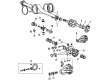
 2001 Toyota Tacoma Differential
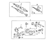
 2001 Toyota Tacoma Universal Joint
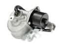 2001 Toyota Tacoma 4WD Actuator
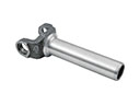 2001 Toyota Tacoma Slip Yoke
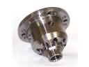
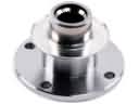 2001 Toyota Tacoma CV Joint Companion Flange
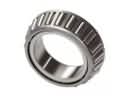 2001 Toyota Tacoma Differential Bearing
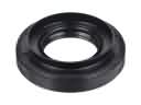 2001 Toyota Tacoma Differential Seal
 2001 Toyota Tacoma Pinion Bearing
 2001 Toyota Tacoma Transfer Case Bearing
 2001 Toyota Tacoma Transfer Case Seal