×
ToyotaParts- Hello
- Login or Register
- Quick Links
- Live Chat
- Track Order
- Parts Availability
- RMA
- Help Center
- Contact Us
- Shop for
- Toyota Parts
- Scion Parts
My Garage
My Account
Cart
OEM 2001 Toyota Sienna Axle Shaft
Car Axle Shaft- Select Vehicle by Model
- Select Vehicle by VIN
Select Vehicle by Model
orMake
Model
Year
Select Vehicle by VIN
For the most accurate results, select vehicle by your VIN (Vehicle Identification Number).
2 Axle Shafts found

 Product Specifications
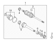
- Other Name: REMAN CV AXLE, LH; CV Axle Assembly; Axle Shaft
- Position: Driver Side
- Replaces: 43420-06070
- Item Weight: 14.50 Pounds
- Item Dimensions: 32.2 x 5.3 x 5.4 inches
- Condition: New
- SKU: 43420-06070-84
- Warranty: This genuine part is guaranteed by Toyota's factory warranty.

 Product Specifications
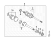
- Other Name: Shaft Assembly, Front Drive; CV Axle Assembly, Front Right; GSP Cv Axle; Axle Shaft; Shaft Assembly, Front Drive, Passenger Side; CV Axle Assembly
- Position: Passenger Side
- Part Name Code: 43410
- Item Weight: 21.40 Pounds
- Item Dimensions: 43.7 x 5.5 x 5.5 inches
- Condition: New
- Fitment Type: Direct Replacement
- SKU: 43410-08010
- Warranty: This genuine part is guaranteed by Toyota's factory warranty.
2001 Toyota Sienna Axle Shaft
Looking for affordable OEM 2001 Toyota Sienna Axle Shaft? Explore our comprehensive catalogue of genuine 2001 Toyota Sienna Axle Shaft. All our parts are covered by the manufacturer's warranty. Plus, our straightforward return policy and speedy delivery service ensure an unparalleled shopping experience. We look forward to your visit!
2001 Toyota Sienna Axle Shaft Parts Q&A
- Q: How to service and repair the axle shaft on 2001 Toyota Sienna?A: Examine the drive shaft for its outboard joint shaft play and test inboard joint shaft glide in thrust direction before checking the inboard joint shaft radial motion and searching for boot damage during inspection. Techs should join the hooks on the large inboard joint boot clamp while cutting the small inboard and two outboard joint boot clamps. The procedure involves marking the joint shafts without damage before inserting the snap ring expander tool to remove the outboard shaft through extension of the snap ring. Unscrew the two boots from their positions while using a screwdriver and hammer to eliminate the inboard joint shaft's dust cover on the LH drive shaft or applying a press for the RH drive shaft. The RH drive shaft requires use of Special Service Tool: 09950-00020 along with a press to disassemble its inboard joint shaft through dust cover removal before snap ring and bearing removal with the press followed by snap ring removal. Mount the outboard joint shaft to a soft jaw vise then detach the No.2 dust deflector from its location using a screwdriver alongside a hammer but avoid harming the ABS speed sensor rotor during this process. The reassembly process involves the installation of new No.2 dust deflector through Special Service Tool: 09309-36010, 09316-20011 and a press. The RH drive shaft inboard joint shaft rebuilding process entails new snap ring, bearing with Special Service Tool: 09223-56010 and a press followed by new dust cover installation. Secure the dust cover for the LH drive shaft by using Special Service Tool: 09223-56010, 09555-55010, and a press while checking that the measured distance from the inboard joint shaft tip matches the specifications. Place vinyl tape on the drive shaft spline before installing new boot clamps and temporary outboard and inboard joint boots by retaining three clamps on both boot ends and the large end. Fit the matchmarks and expand the inboard joint shaft's snap ring to move it into the outboard joint shaft. Starting with outboard boot installation, apply grease between the specified range of 105-125g while building outboard joint and boot connection. In addition, prepare the inboard joint shaft by adding grease amounting to 120.0-130.0g at the joint side with 52.5-57.5g at the boot side before boot assembly. Position boot clamps correctly on the shaft groove at standard drive shaft length before tightening them. Use Special Service Tool: 09521-24010 to secure the clamps by closing the hooks and create a clamp pinch which avoids over-tightening via Special Service Tool: 09240-00020 until you achieve the correct clamp clearance values. Finally, check the drive shaft.
Related 2001 Toyota Sienna Parts
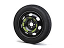 2001 Toyota Sienna Spare Wheel
 2001 Toyota Sienna CV Joint
 2001 Toyota Sienna Sway Bar Bushing
 2001 Toyota Sienna CV Boot
 2001 Toyota Sienna Coil Spring Insulator
 2001 Toyota Sienna Coil Springs
 2001 Toyota Sienna Control Arm Bushing
 2001 Toyota Sienna Shock Absorber
 2001 Toyota Sienna Shock and Strut Boot
 2001 Toyota Sienna Steering Knuckle
 2001 Toyota Sienna Sway Bar Bracket
 2001 Toyota Sienna Transfer Case Output Shaft Snap Ring