×
ToyotaParts- Hello
- Login or Register
- Quick Links
- Live Chat
- Track Order
- Parts Availability
- RMA
- Help Center
- Contact Us
- Shop for
- Toyota Parts
- Scion Parts
My Garage
My Account
Cart
OEM 2001 Toyota Celica Air Bag
Air Bag Module- Select Vehicle by Model
- Select Vehicle by VIN
Select Vehicle by Model
orMake
Model
Year
Select Vehicle by VIN
For the most accurate results, select vehicle by your VIN (Vehicle Identification Number).
1 Air Bag found

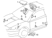
2001 Toyota Celica Passenger Air Bag, Dark Gray
Part Number: 73970-20081-B1$735.99 MSRP: $1078.61You Save: $342.62 (32%)Ships in 1-3 Business DaysProduct Specifications- Other Name: Air Bag Assembly, Instrument Panel; Instrument Panel Air Bag, Upper; Passenger Inflator Module; Air Bag Assembly, Instrument Panel Passenger
- Replaces: 73970-20080-B0, 73970-20081-B0
- Part Name Code: 73970A
- Item Weight: 10.10 Pounds
- Item Dimensions: 16.0 x 11.2 x 8.5 inches
- Condition: New
- Fitment Type: Direct Replacement
- SKU: 73970-20081-B1
- Warranty: This genuine part is guaranteed by Toyota's factory warranty.
2001 Toyota Celica Air Bag
Looking for affordable OEM 2001 Toyota Celica Air Bag? Explore our comprehensive catalogue of genuine 2001 Toyota Celica Air Bag. All our parts are covered by the manufacturer's warranty. Plus, our straightforward return policy and speedy delivery service ensure an unparalleled shopping experience. We look forward to your visit!
2001 Toyota Celica Air Bag Parts Q&A
- Q: What are the crucial steps for safely disposing of a side Air Bag assembly on 2001 Toyota Celica?A: Before discarding a side Air Bag assembly it needs deployment through the specified Special Service Tool: 09082-00700 (SRS Air Bag Deployment Tool) in an open space that maintains minimum distance from residential areas. After deploying an Air Bag 10 meters (33 feet) from the steering wheel pad you should wait for thirty minutes until the Air Bag cools enough for handling. Wear protective gloves together with safety glasses before washing your hands thoroughly with soap and water. The deployment of the Air Bag requires seatback assembly removal then opening the seatback cover fastener followed by proper extraction of the side Air Bag assembly which should face up during storage. Fasten the side Air Bag assembly to a tire by using a minimum 0.0019 square inch (1.25 sq.mm) service-purpose wire harness that will secure the components while deployment occurs. Placing the side Air Bag assembly into the tire should be done with the deployment direction oriented inward and the wire harness needs to be tightly secured to prevent assembly loosening. Begin the Special Service Tool function check by connecting its red clip to the battery positive terminal followed by the black clip to the negative terminal under the condition that the yellow connector must not touch any part of the supplemental restraint system. Users should not operate the tool if the light illuminate during the switch activation process. Two wheels should be securely fastened under and above the tire that contains the side Air Bag assembly through wire harnesses. When attaching the Special Service Tool connectors to the side Air Bag assembly connector users should bypass the secondary lock to protect the connector from harm. Do not expose anyone to the deployment area within 10 meters (33 feet) while operating the activation switch to deploy the Air Bag during which time the LED activated. An operator must wait for the side Air Bag assembly to cool for 30 minutes before removing it from the tire and placing it in a vinyl bag with tight knots for disposal through general waste methods.
Related 2001 Toyota Celica Parts
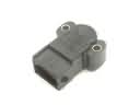 2001 Toyota Celica Throttle Position Sensor
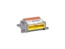 2001 Toyota Celica Air Bag Control Module
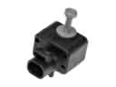 2001 Toyota Celica Air Bag Sensor
 2001 Toyota Celica Brake Light Switch
 2001 Toyota Celica Clock Spring
 2001 Toyota Celica Dimmer Switch
 2001 Toyota Celica Fuel Level Sensor
 2001 Toyota Celica Hazard Warning Switch
 2001 Toyota Celica Horn
 2001 Toyota Celica Ignition Lock Cylinder
 2001 Toyota Celica Knock Sensor
 2001 Toyota Celica Mirror Switch