×
ToyotaParts- Hello
- Login or Register
- Quick Links
- Live Chat
- Track Order
- Parts Availability
- RMA
- Help Center
- Contact Us
- Shop for
- Toyota Parts
- Scion Parts
My Garage
My Account
Cart
OEM 2000 Toyota Solara Wheel Bearing
Hub Bearing- Select Vehicle by Model
- Select Vehicle by VIN
Select Vehicle by Model
orMake
Model
Year
Select Vehicle by VIN
For the most accurate results, select vehicle by your VIN (Vehicle Identification Number).
7 Wheel Bearings found


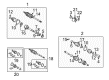
2000 Toyota Solara Bearing (For Front Drive Shaft)
Part Number: 90080-36133$31.18 MSRP: $43.39You Save: $12.21 (29%)Ships in 1-2 Business DaysProduct Specifications- Other Name: Bearing, Radial Ball; Wheel Bearing; Axle Bearing
- Replaces: 90363-41002, 90369-41001
- Part Name Code: 43410C
- Item Weight: 1.10 Pounds
- Item Dimensions: 3.2 x 1.0 x 3.4 inches
- Condition: New
- Fitment Type: Direct Replacement
- SKU: 90080-36133
- Warranty: This genuine part is guaranteed by Toyota's factory warranty.


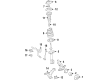
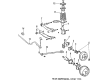
2000 Toyota Solara Wheel Bearings
Part Number: 90369-43008$99.41 MSRP: $139.54You Save: $40.13 (29%)Ships in 1-3 Business DaysProduct Specifications- Other Name: Bearing; Wheel Bearing, Front; Wheel Bearing Kit; Axle Bearing; Front Wheel Bearing; Rear Wheel Bearing; Axle Hub & Shaft Bearings for both sides.
- Manufacturer Note: NSK
- Replaces: 90080-36078, 90080-36021
- Item Weight: 2.20 Pounds
- Item Dimensions: 3.6 x 3.8 x 1.9 inches
- Condition: New
- Fitment Type: Direct Replacement
- SKU: 90369-43008
- Warranty: This genuine part is guaranteed by Toyota's factory warranty.


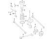
2000 Toyota Solara Hub & Bearing Assembly, Rear Axle, Passenger Side
Part Number: 42450-33020$401.67 MSRP: $588.65You Save: $186.98 (32%)Ships in 1-3 Business DaysProduct Specifications- Other Name: Hub&Bearing Assembly, Rear Axle, Driver Side; Wheel Hub Repair Kit; Axle Bearing
- Manufacturer Note: W(ABS)
- Position: Rear
- Replaces: 42450-07010, 42450-06010
- Item Weight: 7.90 Pounds
- Item Dimensions: 7.1 x 6.9 x 5.1 inches
- Condition: New
- Fitment Type: Direct Replacement
- SKU: 42450-33020
- Warranty: This genuine part is guaranteed by Toyota's factory warranty.


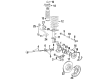
2000 Toyota Solara Front Hub
Part Number: 43502-32070$174.85 MSRP: $249.65You Save: $74.80 (30%)Ships in 1-3 Business DaysProduct Specifications- Other Name: Hub Sub-Assembly, Front Axle; Wheel Hub, Front; Wheel Hub Repair Kit; Wheel Hub Kit; Hub Sub-Assembly, Front Axle, Passenger Side; Hub Sub-Assembly, Front Axle, Driver Side; Wheel Hub
- Manufacturer Note: (J)
- Position: Front
- Replaces: 43502-06010
- Item Weight: 4.40 Pounds
- Item Dimensions: 6.6 x 6.6 x 4.5 inches
- Condition: New
- Fitment Type: Direct Replacement
- SKU: 43502-32070
- Warranty: This genuine part is guaranteed by Toyota's factory warranty.

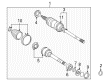
2000 Toyota Solara Inner Shaft Bearing, Front
Part Number: 90369-36001-77$46.22 MSRP: $64.33You Save: $18.11 (29%)Ships in 1-3 Business DaysProduct Specifications- Other Name: Bearing, Ball, 36, 67, K; CV Axle Shaft Carrier Bearing, Front; Wheel Bearing; Axle Bearing; Bearing
- Position: Front
- Replaces: 90080-36048, 90369-36001
- Item Weight: 1.10 Pounds
- Item Dimensions: 4.8 x 4.3 x 2.9 inches
- Condition: New
- SKU: 90369-36001-77
- Warranty: This genuine part is guaranteed by Toyota's factory warranty.

2000 Toyota Solara Hub Assembly
Part Number: 42410-33040$415.97 MSRP: $609.60You Save: $193.63 (32%)Ships in 1-3 Business DaysProduct Specifications- Other Name: Hub&Bearing Assembly; Rear Wheel Bearing & Hub; Wheel Hub Repair Kit; Axle Bearing; Hub & Bearing; Rear Axle Assembly, Passenger & Driver Side; Wheel Bearing and Hub Assembly.
- Replaces: 42410-07010, 42410-06020
- Item Weight: 7.70 Pounds
- Item Dimensions: 6.6 x 4.7 x 6.5 inches
- Condition: New
- Fitment Type: Direct Replacement
- SKU: 42410-33040
- Warranty: This genuine part is guaranteed by Toyota's factory warranty.


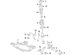
2000 Toyota Solara Hub Sub-Assembly, Front Axle, Passenger Side
Part Number: 43502-06040$162.49 MSRP: $230.03You Save: $67.54 (30%)Product Specifications- Other Name: Hub Sub-Assembly, Front Axle; Hub Sub-Assembly, Front Axle, Driver Side; Wheel Hub Repair Kit; Wheel Hub
- Position: Front
- Replaces: 43502-33030, 43502-33010, 43502-06020
- Item Weight: 5.00 Pounds
- Item Dimensions: 6.7 x 6.7 x 4.8 inches
- Condition: New
- Fitment Type: Direct Replacement
- SKU: 43502-06040
- Warranty: This genuine part is guaranteed by Toyota's factory warranty.
2000 Toyota Solara Wheel Bearing
Looking for affordable OEM 2000 Toyota Solara Wheel Bearing? Explore our comprehensive catalogue of genuine 2000 Toyota Solara Wheel Bearing. All our parts are covered by the manufacturer's warranty. Plus, our straightforward return policy and speedy delivery service ensure an unparalleled shopping experience. We look forward to your visit!
2000 Toyota Solara Wheel Bearing Parts Q&A
- Q: How to service and repair the wheel bearing on 2000 Toyota Solara?A: You should start servicing or repairing the wheel bearing by taking out the front wheel. Test the bearing backlash and axle hub deviation by taking off both bolts along with brake caliper and disc before properly supporting the brake caliper. A dial indicator should measure backlash at the center of the axle hub because excessive 0.05 mm (0.0020 inch) backlash warrants bearing replacement. Measure the deviation on the axle hub surface beyond the hub bolt which should be less than 0.05 mm (0.0020 inch); if not replace the axle hub. Reinstall the disc followed by the brake caliper and both bolts while torquing them to 107 Nm (1,090 kgf-cm, 79 ft. lbs.). After removing the cotter pin and lock cap from the drive shaft lock nut position, personnel should use brakes during the nut's removal procedure. Repeat this process by taking out the two bolts on the brake caliper along with the disc before safely positioning the brake caliper. To disconnect the ABS speed sensor you must remove the bolt that fastens the wire harness clamp. Use Special Service Tool: 09610-20012 to disconnect the tie rod end from the steering knuckle through removal of its nut and cotter pin. Lower suspension arm needs disconnecting from the lower ball joint through removal of its bolt and two nuts. Procure the steering knuckle with axle hub by first disassembling its two nuts and bolts while maintaining safety of the boot and ABS speed sensor rotor. Put the steering knuckle with axle hub into position first while watching for boot and ABS speed sensor rotor damage then apply engine oil to the 2 nuts and use the 2 bolts and nuts on the shock absorber's lower side before torquing to 220 Nm (2,250 kgf-cm, 162 ft. lbs.). Install and torques the lower suspension arm toward the lower ball joint at 127 Nm (1,300 kgf-cm, 94 ft. lbs.). Install the steering knuckle-tie rod end connection before adding a new cotter pin with the nut. Tighten the nut by a further 60 degrees beyond the correct position if the holes do not match. Torque the nut until its measurement reaches 49 Nm (500 kgf-cm, 36 ft. lbs.). Fasten the ABS speed sensor along with its wire harness clamp using 8.0 Nm (82 kgf-cm) torque value (71 inch lbs). First reinstall the disc along with the brake caliper nut along with two bolts at 107 Nm (1,090 kgf-cm, 79 ft. lbs.) torque. Then tighten the brake nut to 294 Nm (3,000 kgf-cm, 217 ft. lbs.) with applied brakes. Afterward, install the lock cap then a new cotter pin while adding an additional 600 torque on the nut when the holes are misaligned. Begin by measuring bearing backlash and axle hub deviation before tightening the front wheel with 103 Newton meters (1,050 kilogram feet centimeters or 76 foot pounds). Afterwards use the brake pedal several times then verify front wheel alignment and ABS speed sensor signal.
Related 2000 Toyota Solara Parts
 2000 Toyota Solara Backing Plate
 2000 Toyota Solara Brake Caliper
 2000 Toyota Solara Brake Caliper Bracket
 2000 Toyota Solara Brake Disc
 2000 Toyota Solara Brake Drum
 2000 Toyota Solara Brake Pad Set
 2000 Toyota Solara Brake Shoe Set
 2000 Toyota Solara Hydraulic Hose
 2000 Toyota Solara Parking Brake Shoe
 2000 Toyota Solara Spindle Nut
 2000 Toyota Solara Wheel Cylinder Repair Kit
 2000 Toyota Solara Wheel Hub