×
ToyotaParts- Hello
- Login or Register
- Quick Links
- Live Chat
- Track Order
- Parts Availability
- RMA
- Help Center
- Contact Us
- Shop for
- Toyota Parts
- Scion Parts
My Garage
My Account
Cart
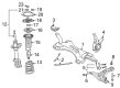
OEM 2000 Toyota MR2 Spyder Control Arm
Suspension Arm- Select Vehicle by Model
- Select Vehicle by VIN
Select Vehicle by Model
orMake
Model
Year
Select Vehicle by VIN
For the most accurate results, select vehicle by your VIN (Vehicle Identification Number).
2 Control Arms found


2000 Toyota MR2 Spyder Lower Control Arm, Driver Side
Part Number: 48069-19156$257.08 MSRP: $367.06You Save: $109.98 (30%)Ships in 1-3 Business DaysProduct Specifications- Other Name: Arm Sub-Assembly, Suspension; Suspension Control Arm, Front Left; Control Arm Assembly; Arm Sub-Assembly, Front Suspension, Lower Driver Side; Control Arm
- Position: Lower Driver Side
- Replaces: 48069-19155
- Part Name Code: 48069
- Item Weight: 9.30 Pounds
- Item Dimensions: 18.2 x 12.3 x 4.6 inches
- Condition: New
- Fitment Type: Direct Replacement
- SKU: 48069-19156
- Warranty: This genuine part is guaranteed by Toyota's factory warranty.

2000 Toyota MR2 Spyder Lower Control Arm, Passenger Side
Part Number: 48068-19176$257.08 MSRP: $367.06You Save: $109.98 (30%)Ships in 1-3 Business DaysProduct Specifications- Other Name: Arm Sub-Assembly, Suspension; Suspension Control Arm, Front Right; Control Arm Assembly; Arm Sub-Assembly, Front Suspension, Lower Passenger Side; Control Arm
- Position: Passenger Side
- Replaces: 48068-19175
- Part Name Code: 48068
- Item Weight: 9.30 Pounds
- Item Dimensions: 18.1 x 12.4 x 4.5 inches
- Condition: New
- Fitment Type: Direct Replacement
- SKU: 48068-19176
- Warranty: This genuine part is guaranteed by Toyota's factory warranty.
2000 Toyota MR2 Spyder Control Arm
Looking for affordable OEM 2000 Toyota MR2 Spyder Control Arm? Explore our comprehensive catalogue of genuine 2000 Toyota MR2 Spyder Control Arm. All our parts are covered by the manufacturer's warranty. Plus, our straightforward return policy and speedy delivery service ensure an unparalleled shopping experience. We look forward to your visit!
2000 Toyota MR2 Spyder Control Arm Parts Q&A
- Q: How to service and repair the front control arm on 2000 Toyota MR2 Spyder?A: Start the front control arm service process by removing the front wheel followed by unfastening the stabilizer bar link through stabilizer bar nut removal; in this case hold the stud with a 5mm hexagon wrench when the ball joint rotates with the nut. Start by removing the brake caliper and disc through the removal of two bolts followed by proper support for the caliper. Start by disconnecting the ABS speed sensor connector and proceed to disconnect the axle hub front assembly by removing its 4 bolts together with the hub assembly and dust cover. First disconnect the lower suspension arm from the steering knuckle by removing both nut and cotter pin followed by application of Special Service Tool: 09628-62011 for proper disconnection. Unfasten and collect the 4 bolts, nut and suspension member brace and front lower suspension arm from the system while avoiding turning the nut. Before installing the nut inspect the ball joint boot while checking the ball joint movement by rotating the stud five times then use a torque wrench to measure a turning torque of 0.59 - 3.43 Nm (6 - 35 kgf-cm, 5.2 - 30 inch lbs.). When using a fresh lower suspension arm for installation, install a new washer through Special Service Tool using a wooden block and press. First install the lower suspension arm along with its suspension member brace by using the four bolts and nuts before tightening bolt A to 73 Nm (745 kgf-cm, 54 ft. lbs.) while tightening bolt B to 87 Nm (887 kgf-cm, 64 ft. lbs.) and bolts C to 75 Nm (765 kgf-cm, 55 ft. lbs.). The lower suspension arm must be fastened to the steering knuckle with a nut that should be tightened to 98 Nm (1,000 kgf-cm, 72 ft. lbs.) while a new cotter pin is mounted before increasing the nut torque up to 60 degrees if holes do not align. Install the dust cover along with the axle hub by using the 4 bolts while torquing them to 56 Nm (571 kgf-cm, 41 ft. lbs.). Reconnect the ABS speed sensor connector after completing this step. Secure the disc along with brake caliper by using the two bolts and tightening them to specifications of 109 Nm (1,112 kgf-cm, 80 ft. lbs.). The next step is to attach the stabilizer bar link with three retainers and two cushions to the lower suspension arm using a nut torqued up to 18 Nm (184 kgf-cm, 13 ft. lbs.). Finish by connecting the stabilizer bar link to the stabilizer bar by using a nut torqued up to 44 Nm (449 kgf-cm, 32 ft. lbs.). After replacing the front wheel you must torque its fasteners to 103 Nm (1,050 kgf-cm, 76 ft. lbs.).
Related 2000 Toyota MR2 Spyder Parts
 2000 Toyota MR2 Spyder Alignment Bolt
 2000 Toyota MR2 Spyder Bump Stop
 2000 Toyota MR2 Spyder Coil Spring Insulator
 2000 Toyota MR2 Spyder Coil Springs
 2000 Toyota MR2 Spyder Control Arm Bolt
 2000 Toyota MR2 Spyder Front Cross-Member
 2000 Toyota MR2 Spyder Shock And Strut Mount
 2000 Toyota MR2 Spyder Steering Knuckle
 2000 Toyota MR2 Spyder Strut Housing
 2000 Toyota MR2 Spyder Sway Bar Bracket
 2000 Toyota MR2 Spyder Sway Bar Bushing
 2000 Toyota MR2 Spyder Sway Bar Kit