×
ToyotaParts- Hello
- Login or Register
- Quick Links
- Live Chat
- Track Order
- Parts Availability
- RMA
- Help Center
- Contact Us
- Shop for
- Toyota Parts
- Scion Parts
My Garage
My Account
Cart
OEM 2000 Toyota Land Cruiser Alternator
Generator- Select Vehicle by Model
- Select Vehicle by VIN
Select Vehicle by Model
orMake
Model
Year
Select Vehicle by VIN
For the most accurate results, select vehicle by your VIN (Vehicle Identification Number).
1 Alternator found


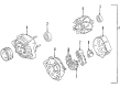
2000 Toyota Land Cruiser Alternator Assembly, With Regulator
Part Number: 27060-50260-84$144.80 MSRP: $190.45You Save: $45.65 (24%)Ships in 1-3 Business DaysProduct Specifications- Other Name: REMAN ALTERNATOR ASS; Alternator
- Replaces: 27060-50260
- Item Weight: 16.60 Pounds
- Item Dimensions: 9.7 x 7.6 x 7.1 inches
- Condition: New
- SKU: 27060-50260-84
- Warranty: This genuine part is guaranteed by Toyota's factory warranty.
2000 Toyota Land Cruiser Alternator
Looking for affordable OEM 2000 Toyota Land Cruiser Alternator? Explore our comprehensive catalogue of genuine 2000 Toyota Land Cruiser Alternator. All our parts are covered by the manufacturer's warranty. Plus, our straightforward return policy and speedy delivery service ensure an unparalleled shopping experience. We look forward to your visit!
2000 Toyota Land Cruiser Alternator Parts Q&A
- Q: How to disassemble and reassemble the Alternator, including the steps for replacing the front and rear bearings on 2000 Toyota Land Cruiser?A: Disassembly of the generator begins with removing the 100 A model generator cover and cord clip using bolt and nut tools while models without Canada specifications require only bolt and cord clip removal. The next step requires removing the rear end cover through this sequence: First separate the nut and terminal insulator and three nuts followed by unfastening the two nuts and bolt and plate terminal. The brush holder cover requires removal first before subsequent removal of five screws, brush holder and voltage regulator followed by extraction of the seal plate from the rectifier end frame. The four screws allow removal of the rectifier holder along with its attached four rubber insulators. Use Special Service Tool 09820-63010 with a torque wrench and tighten the socket clockwise to 39 Nm (400 kgf.cm, 29 ft.lbf) while securing the tool to the rotor shaft and mount the adapter into a vise before installing the generator to the adapter. The pulley nut can be loosened through counter-clockwise tool rotation yet careful not to exceed a half turn since it might damage the rotor shaft. Following this step, remove the generator together with the tool from the adapter. Special Service Tool 09286-46011 removes the rectifier end frame along with the generator washer after disconnecting nuts and cord clip fittings on the 80 A model while leaving only the nuts exposed for the 100 A model. The drive end frame should be placed on the pulley followed by the rotor installation before setting the rectifier end frame and applying the generator washer on the rotor followed by frame press-in using a 29 mm socket wrench. When installing the cord plug together with four nuts on the 80 A model maintain a torque of 4.5 Nm (46 kg.cm, 40 in.lb) yet install these four nuts only for the 100 A model with the same torque value. Use the pulley holding tool to fasten the nut after manual tightening and verify its security at 39 N.m (400 kgf.cm, 29 ft.lbf). Move the generator to the adapter once you tighten the pulley nut to 110.5 N.m (1,128 kgf.cm, 81 ft.lbf). Fasten the rectifier holder to its place using four rubber insulators while tightening the four screws to 2.94 Nm (30 kg.cm, 26 in.lb). Screw the seal plate onto the rectifier end frame afterwards add the voltage regulator and brush holder in the correct position using five 2.0 Nm (20 kg.cm, 17 in.lb) torques. The rear end cover requires two nuts and one bolt for assembly while the bolt gets torqued at 3.8 Nm (39 kg.cm, 34 in.lb) and the nuts reach 4.4 Nm (45 kg.cm, 39 in.lb) before installing the terminal insulator with a nut at 4.1 Nm (42 kg.cm, 36 in.lb). The 100 A model requires users to fasten the generator cover with cord clip through a bolt and nut at 16.6 Nm (170 kg.cm, 12 ft.lb) for Canada and without the bolt for non-Canada versions. Verify the rotor moves without resistance during its rotation. A new front bearing requires removal of four screws and bearing retainer before expulsion through Special Service Tool O9950-60010 (09951-00260, 09952-06010). Insert the new bearing with Special Service Tool 09950-60010 (09951-00500) and fasten the bearing retainer with four screws at 3.0 Nm (31 kg.cm, 27 in.lb). The correct substitution method for the rear bearing starts with disassembly of bearing cover and bearing using Special Service Tool 09820-00021 followed by applying the inside bearing cover to the rotor before using Special Service Tool 09820-00030 to insert the new bearing and finally using Special Service Tool 09285-76010 to install the outer bearing cover.
Related 2000 Toyota Land Cruiser Parts
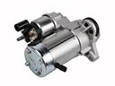 2000 Toyota Land Cruiser Starter Motor
 2000 Toyota Land Cruiser Alternator Bearing
 2000 Toyota Land Cruiser Alternator Brush
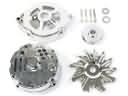 2000 Toyota Land Cruiser Alternator Case Kit
 2000 Toyota Land Cruiser Alternator Pulley
 2000 Toyota Land Cruiser Armature
 2000 Toyota Land Cruiser Battery Terminal
 2000 Toyota Land Cruiser Battery Tray
 2000 Toyota Land Cruiser Car Batteries
 2000 Toyota Land Cruiser Starter Drive Gear
 2000 Toyota Land Cruiser Starter Solenoid
 2000 Toyota Land Cruiser Voltage Regulator