×
ToyotaParts- Hello
- Login or Register
- Quick Links
- Live Chat
- Track Order
- Parts Availability
- RMA
- Help Center
- Contact Us
- Shop for
- Toyota Parts
- Scion Parts
My Garage
My Account
Cart
OEM 2000 Toyota Celica Starter Motor
Starter Ignition- Select Vehicle by Model
- Select Vehicle by VIN
Select Vehicle by Model
orMake
Model
Year
Select Vehicle by VIN
For the most accurate results, select vehicle by your VIN (Vehicle Identification Number).
4 Starter motors found

2000 Toyota Celica Starter
Part Number: 28100-22070-84$208.11 MSRP: $295.92You Save: $87.81 (30%)Ships in 1-3 Business DaysProduct Specifications- Other Name: Reman Starter; Starter Motor
- Replaces: 28100-22070
- Item Weight: 11.10 Pounds
- Item Dimensions: 16.1 x 8.6 x 8.4 inches
- Condition: New
- SKU: 28100-22070-84
- Warranty: This genuine part is guaranteed by Toyota's factory warranty.
2000 Toyota Celica Starter
Part Number: 28100-22050-84$208.11 MSRP: $295.92You Save: $87.81 (30%)Ships in 1-3 Business DaysProduct Specifications- Other Name: Reman Starter; Starter Motor
- Replaces: 28100-22050
- Item Weight: 11.90 Pounds
- Item Dimensions: 16.1 x 8.8 x 8.3 inches
- Condition: New
- SKU: 28100-22050-84
- Warranty: This genuine part is guaranteed by Toyota's factory warranty.
- Product Specifications
- Other Name: Reman Starter Assembly; Starter Motor
- Replaces: 28100-22080
- Item Weight: 9.20 Pounds
- Item Dimensions: 10.5 x 7.4 x 5.3 inches
- Condition: New
- SKU: 28100-22080-84
- Warranty: This genuine part is guaranteed by Toyota's factory warranty.

 Product Specifications
- Other Name: Reman Starter Assembly; Starter Motor
- Replaces: 28100-22060
- Item Weight: 9.30 Pounds
- Item Dimensions: 10.3 x 7.1 x 5.1 inches
- Condition: New
- SKU: 28100-22060-84
- Warranty: This genuine part is guaranteed by Toyota's factory warranty.
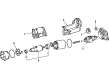
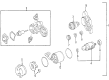
2000 Toyota Celica Starter Motor
Looking for affordable OEM 2000 Toyota Celica Starter Motor? Explore our comprehensive catalogue of genuine 2000 Toyota Celica Starter Motor. All our parts are covered by the manufacturer's warranty. Plus, our straightforward return policy and speedy delivery service ensure an unparalleled shopping experience. We look forward to your visit!
2000 Toyota Celica Starter Motor Parts Q&A
- Q: How to service and repair the starter motor on 2000 Toyota Celica?A: The service and repair of a starter motor begins with the following sequence of steps: remove the field frame with armature from the magnetic switch assembly through a process of disconnecting the lead wire from the magnetic switch terminal followed by removal of 2 through bolts and subsequent removal of 2 screws and end cover from the field frame. The O-ring should be removed first from the field frame while using a screwdriver to disconnect the brush from the brush holder followed by brushing away the four brush attachments and removing the brush holder. The procedure starts with removing the field frame segment from the magnetic switch assembly while discarding the O-ring. Begin the process by removing the starter housing clutch assembly and gears through disassembly of the 2 bolts (5.9 Nm (60 kg.cm, 52 in.lb)). Then separate these components from the magnetic switch assembly. A magnetic finger must remove the steel ball which sits inside the clutch shaft hole. People should pull the armature from the magnetic switch assembly (1ZZ-FE) while 2ZZ-GE owners need a press tool to do the job. Use Special Service Tool: 09286-46011 for removal and Special Service Tool: 09820-00030 along with a press to exchange bearings while testing them through hand manipulation; any bearing resistance requires a new bearing instance. First remove the end cover by unscrewing its 3 bolts then taking out the plunger and end cover combined with gasket. Prepare the contact plate for inspection through vernier calibration (maximum tolerance 0.9 millimeters (0.035 inches)). Replace the contact plate if necessary. The terminal nuts should be loosened first using Special Service Tool: 09810-38140 before removing Terminal C and Terminal 30 with their respective nuts, wave washers and terminal insulators, O-rings along with terminal bolts and contact plates. Install new parts while maintaining the correct orientation of terminal insulators. A wooden block (20 x 37 x 40 mm (0.79 x 1.46 x 1.57 in.)) should be used to apply 981 N (100 kg, 221 lb) pressure on the contact plate when pressing down before nut tightening to 17 Nm (173 kg.cm, 12 ft.lb). Install the magnetic switch end cover by placing the plunger inside and setting in the new gasket and 3 bolts (Torque: 2.5 Nm (26 kg.cm, 23 in.lb)). The reassembly process starts with high-temperature grease application to bearings and gears followed by armature installation to magnetic switch assembly (2ZZ-GE needs the front bearing in its correct position) and then insertion of a grease-coated steel ball into the clutch shaft hole and finally the starter housing installation using a new O-ring along with starter clutch assembly idler gear and bearing which must be secured with two screws (Torque: 9.3 Nm (95 kg.cm, 82 in.lb)) Add the newly installed O-ring to the field frame before lining it up with the magnetic switch and correctly mounting it. Install the brush holder on the field frame then connect the brushes by holding the brush spring back while maintaining the positive lead wires in a non-grounded position. The procedure includes installing a new O-ring to the field frame while using 2 screws (Torque: 3.8 Nm (39 kg.cm, 34 in.lb)) to attach the end cover then applying 2 through bolts (Torque: 9.3 Nm (95 kg.cm, 82 in.lb)) to secure the assembly before connecting the lead wire to terminal C with a nut (Torque: 5.9 Nm (60 kg.cm, 52 in.lb)). You should complete the process by adding a new dust protector.
Related 2000 Toyota Celica Parts
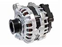 2000 Toyota Celica Alternator
 2000 Toyota Celica Starter Solenoid
 2000 Toyota Celica Alternator Bearing
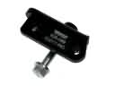 2000 Toyota Celica Alternator Bracket
 2000 Toyota Celica Alternator Pulley
 2000 Toyota Celica Armature
 2000 Toyota Celica Battery Cable
 2000 Toyota Celica Battery Terminal
 2000 Toyota Celica Battery Tray
 2000 Toyota Celica Starter Brush
 2000 Toyota Celica Starter Drive Gear
 2000 Toyota Celica Voltage Regulator