×
ToyotaParts- Hello
- Login or Register
- Quick Links
- Live Chat
- Track Order
- Parts Availability
- RMA
- Help Center
- Contact Us
- Shop for
- Toyota Parts
- Scion Parts
My Garage
My Account
Cart
OEM 2000 Toyota Celica Brake Caliper
Caliper- Select Vehicle by Model
- Select Vehicle by VIN
Select Vehicle by Model
orMake
Model
Year
Select Vehicle by VIN
For the most accurate results, select vehicle by your VIN (Vehicle Identification Number).
6 Brake Calipers found


2000 Toyota Celica Caliper, Passenger Side
Part Number: 47730-20630$141.46 MSRP: $200.25You Save: $58.79 (30%)Ships in 1-3 Business DaysProduct Specifications- Other Name: Cylinder Assembly, Disc; Disc Brake Caliper, Rear Right; Cylinder Assembly, Rear Disc Brake, Passenger Side; Brake Caliper
- Position: Passenger Side
- Part Name Code: 47730B
- Item Weight: 5.30 Pounds
- Condition: New
- Fitment Type: Direct Replacement
- SKU: 47730-20630
- Warranty: This genuine part is guaranteed by Toyota's factory warranty.
2000 Toyota Celica Caliper, Rear Driver Side
Part Number: 47750-20620$141.46 MSRP: $200.25You Save: $58.79 (30%)Ships in 1-2 Business DaysProduct Specifications- Other Name: Cylinder Assembly, Disc; Disc Brake Caliper, Rear Left; Cylinder Assembly, Disc Brake, Rear Driver Side; Brake Caliper
- Position: Rear Driver Side
- Part Name Code: 47750A
- Item Weight: 5.10 Pounds
- Condition: New
- Fitment Type: Direct Replacement
- SKU: 47750-20620
- Warranty: This genuine part is guaranteed by Toyota's factory warranty.

2000 Toyota Celica Caliper, Passenger Side
Part Number: 47730-20610$263.39 MSRP: $376.07You Save: $112.68 (30%)Ships in 1-3 Business DaysProduct Specifications- Other Name: Cylinder Assembly, Disc; Disc Brake Caliper, Front Right; Cylinder Assembly, Front Disc Brake, Passenger Side; Brake Caliper
- Position: Passenger Side
- Part Name Code: 47730
- Item Weight: 12.00 Pounds
- Item Dimensions: 9.9 x 7.5 x 5.5 inches
- Condition: New
- Fitment Type: Direct Replacement
- SKU: 47730-20610
- Warranty: This genuine part is guaranteed by Toyota's factory warranty.
2000 Toyota Celica Caliper, Driver Side
Part Number: 47750-20600$258.23 MSRP: $368.69You Save: $110.46 (30%)Ships in 1-3 Business DaysProduct Specifications- Other Name: Cylinder Assembly, Disc; Disc Brake Caliper, Front Left; Cylinder Assembly, Disc Brake, Driver Side; Brake Caliper
- Position: Driver Side
- Part Name Code: 47750
- Item Weight: 12.30 Pounds
- Item Dimensions: 10.2 x 7.5 x 5.3 inches
- Condition: New
- Fitment Type: Direct Replacement
- SKU: 47750-20600
- Warranty: This genuine part is guaranteed by Toyota's factory warranty.
2000 Toyota Celica Caliper, Driver Side
Part Number: 47750-20510$185.76 MSRP: $265.23You Save: $79.47 (30%)Ships in 1-3 Business DaysProduct Specifications- Other Name: Cylinder Assembly, Disc; Disc Brake Caliper, Front Left; Cylinder Assembly, Disc Brake, Driver Side; Brake Caliper
- Position: Driver Side
- Part Name Code: 47750
- Item Weight: 12.00 Pounds
- Item Dimensions: 10.0 x 7.7 x 5.4 inches
- Condition: New
- Fitment Type: Direct Replacement
- SKU: 47750-20510
- Warranty: This genuine part is guaranteed by Toyota's factory warranty.
2000 Toyota Celica Caliper, Passenger Side
Part Number: 47730-20600$185.76 MSRP: $265.23You Save: $79.47 (30%)Ships in 1-3 Business DaysProduct Specifications- Other Name: Cylinder Assembly, Disc; Disc Brake Caliper, Front Right; Cylinder Assembly, Front Disc Brake, Passenger Side; Brake Caliper
- Position: Passenger Side
- Part Name Code: 47730
- Item Weight: 11.60 Pounds
- Item Dimensions: 10.1 x 7.5 x 5.5 inches
- Condition: New
- Fitment Type: Direct Replacement
- SKU: 47730-20600
- Warranty: This genuine part is guaranteed by Toyota's factory warranty.
2000 Toyota Celica Brake Caliper
Looking for affordable OEM 2000 Toyota Celica Brake Caliper? Explore our comprehensive catalogue of genuine 2000 Toyota Celica Brake Caliper. All our parts are covered by the manufacturer's warranty. Plus, our straightforward return policy and speedy delivery service ensure an unparalleled shopping experience. We look forward to your visit!
2000 Toyota Celica Brake Caliper Parts Q&A
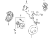
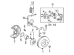
- Q: How to service and repair the brake caliper on 2000 Toyota Celica?A: You can begin service and repair of brake calipers on both 1ZZ-FE and 2ZZ-GE engines through the removal of the set ring and cylinder boot using a screwdriver. First put a cloth between the piston and caliper after which compressed air should be used to remove the piston with fingers kept away from dangerous areas. Start by removing the piston seal using a screwdriver and after that remove both sliding pins which will be found on the torque plate. The correct method for both engines requires you to remove dust boots from 1ZZ-FE but you need to tap out 2ZZ-GE dust boots with a screwdriver combined with a hammer. Apply a 19 mm socket wrench to install new dust boots on the torque plate while making sure the metal plate lies in a tight position. Measure pad lining thickness with a ruler to check if the pads require replacement due to minimum 1.0 mm thickness or severe wear or if the lining is under standard thickness which amounts to 11.0 mm for the 1ZZ-FE engine and 11.5 mm for the 2ZZ-GE engine. Use a micrometer to examine disc thickness since the standard value is 25.0 mm but the minimum stands at 23.0 mm. Obtain new parts or conduct disc grinding if the measurement reaches or drops below the minimum threshold or reveals uneven damage. The disc runout must be checked using a dial indicator 10 mm from the edge and should not exceed 0.05 mm maximum; bearing play and axle hub runout must be inspected while needing disc adjustment or grinding for correction. After removing the knuckle torque plate along with two bolts and the disc and hub nuts, adjust the disc placement by rotating it by 1/5 of its initial position before tightening hub nuts to 103 Nm. Measure the runout again while tracking the minimum reading and the disc position before moving to check the remaining knuckle hubs. Installation of the disc will occur at its position showing the minimum runout value below 0.05 mm but you should replace the disc when the runout exceeds this mark. The torque plate installation should be followed by tightening the mounting bolts to 107 Nm value while lubricating indicated components with lithium soap base glycol grease.
Related 2000 Toyota Celica Parts
 2000 Toyota Celica Wheel Hub
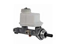 2000 Toyota Celica Brake Master Cylinder
 2000 Toyota Celica Backing Plate
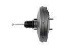 2000 Toyota Celica Brake Booster
 2000 Toyota Celica Brake Caliper Bracket
 2000 Toyota Celica Brake Disc
 2000 Toyota Celica Brake Master Cylinder Reservoir
 2000 Toyota Celica Brake Shoe Set
 2000 Toyota Celica Master Cylinder Repair Kit
 2000 Toyota Celica Parking Brake Shoe
 2000 Toyota Celica Spindle Nut
 2000 Toyota Celica Wheel Cylinder