×
ToyotaParts- Hello
- Login or Register
- Quick Links
- Live Chat
- Track Order
- Parts Availability
- RMA
- Help Center
- Contact Us
- Shop for
- Toyota Parts
- Scion Parts
My Garage
My Account
Cart
OEM Toyota Celica Brake Pads
Disc Brake Pad Set- Select Vehicle by Model
- Select Vehicle by VIN
Select Vehicle by Model
orMake
Model
Year
Select Vehicle by VIN
For the most accurate results, select vehicle by your VIN (Vehicle Identification Number).
15 Brake Pads found
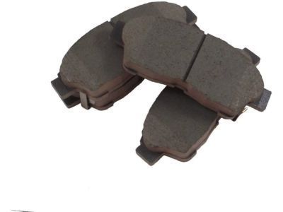
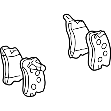
Toyota Celica Pad Kit, Disc Brake Part Number: 04466-32050
$46.47 MSRP: $64.61You Save: $18.14 (29%)Ships in 1-2 Business Days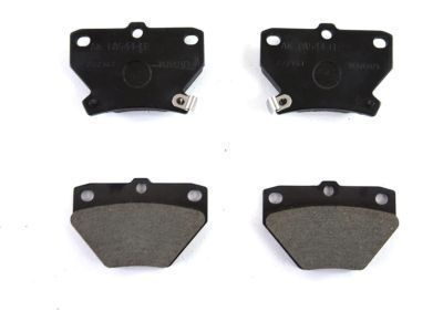
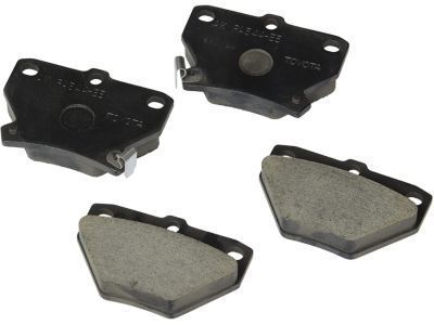
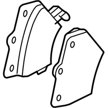
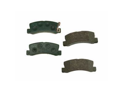
Toyota Celica Brake Pads, Rear Part Number: 04466-20090
$38.71 MSRP: $53.81You Save: $15.10 (29%)Ships in 1-2 Business Days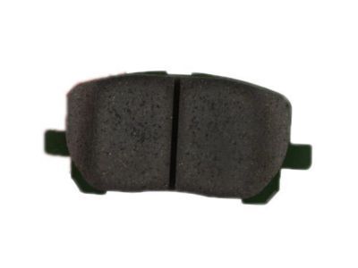
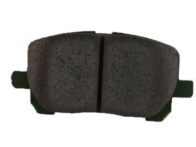
Toyota Celica Brake Pads, Front Part Number: 04465-2B010
$46.47 MSRP: $64.61You Save: $18.14 (29%)Ships in 1 Business Day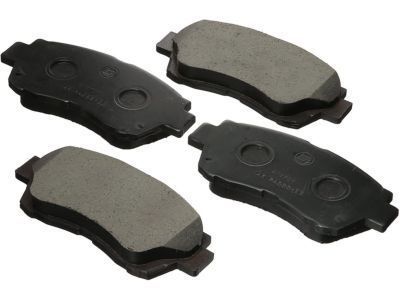
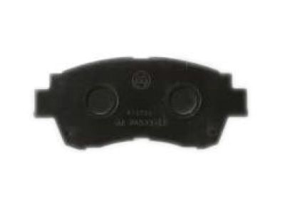
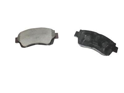
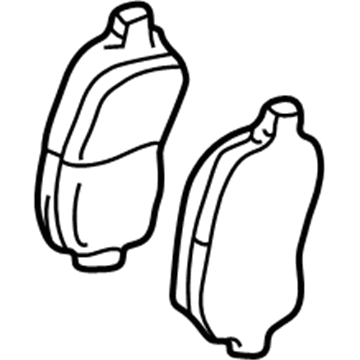
Toyota Celica Pad Kit, Disc Brake, Front Part Number: 04465-33060
$75.25 MSRP: $104.50You Save: $29.25 (28%)Ships in 1-3 Business Days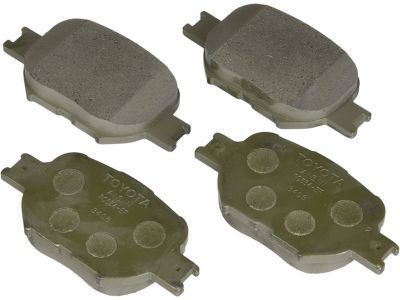
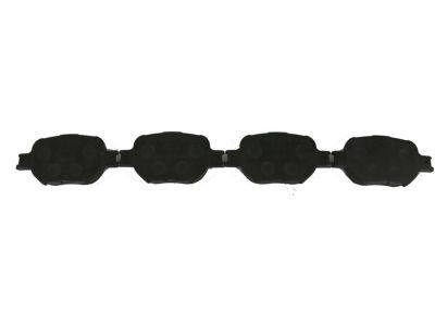
Toyota Celica Brake Pads, Front Part Number: 04465-20540
$46.47 MSRP: $64.61You Save: $18.14 (29%)Ships in 1 Business Day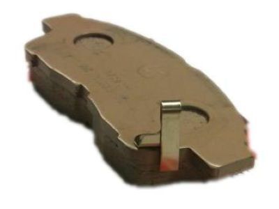
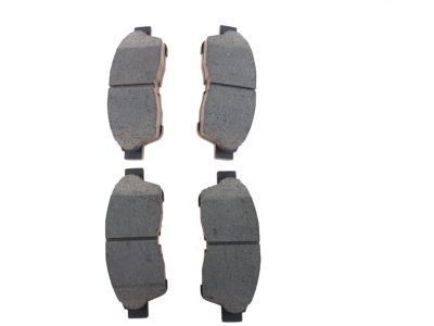
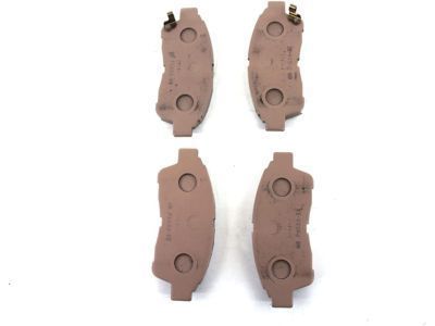
Toyota Celica Brake Pads Part Number: 04465-33021
$76.07 MSRP: $105.63You Save: $29.56 (28%)Ships in 1-3 Business DaysToyota Celica Brake Pads Part Number: 04465-47030
$42.65 MSRP: $59.30You Save: $16.65 (29%)Ships in 1-3 Business Days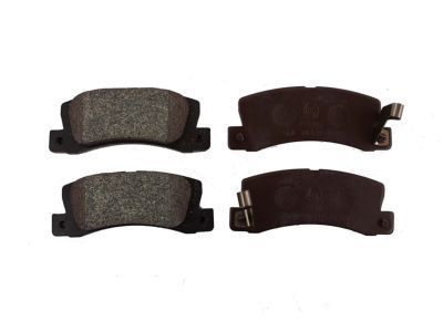
Toyota Celica Brake Pads, Rear Part Number: 04466-20020
$46.47 MSRP: $64.61You Save: $18.14 (29%)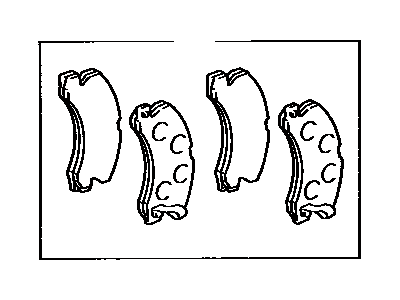
Toyota Celica Pads, Rear Part Number: 04466-22110
$42.65 MSRP: $59.30You Save: $16.65 (29%)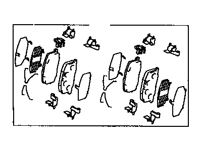
Toyota Celica Front Pads Part Number: 04465-YZZB4
$45.30 MSRP: $63.08You Save: $17.78 (29%)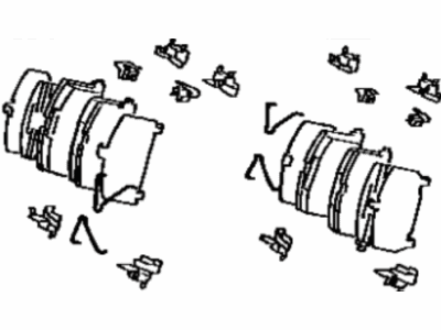
Toyota Celica Brake Pads Part Number: 04465-YZZA2
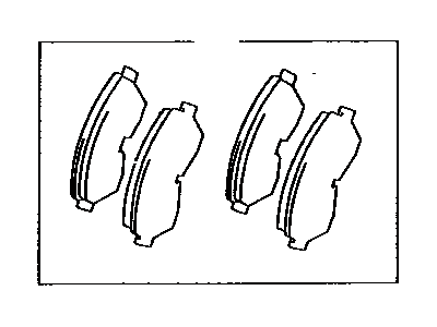
Toyota Celica Brake Pads Part Number: 04465-YZZA3
Toyota Celica Front Pads Part Number: 04465-20430
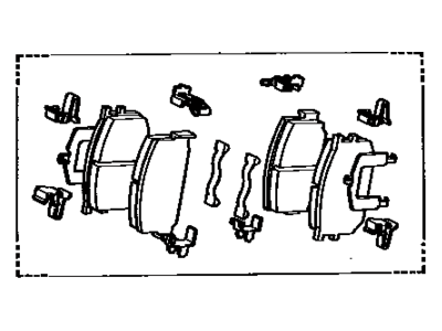
Toyota Celica Front Pads Part Number: 04465-YZZB7
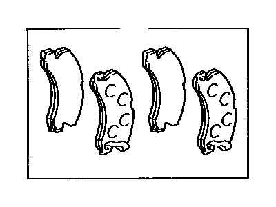
Toyota Celica Brake Pads, Rear Part Number: 04466-33010
Toyota Celica Brake Pads
Choose genuine Brake Pads that pass strict quality control tests. You can trust the top quality and lasting durability. Shopping for OEM Brake Pads for your Toyota Celica? Our website is your one-stop destination. We stock an extensive selection of genuine Toyota Celica parts. The price is affordable so you can save more. It only takes minutes to browse and find the exact fit. Easily add to cart and check out fast. Our hassle-free return policy will keep you stress-free. We process orders quickly for swift delivery. Your parts will arrive faster, so you can get back on the road sooner.
Toyota Celica Brake Pads Parts and Q&A
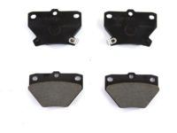
- Q:How to replace the rear Brake Pads on Toyota Celica?A:You need to start pad replacement by removing the rear wheel to measure pad lining thickness which must remain above 1.0 mm (0.039 inch). Proceed by removing the clip and 2 anti-rattle springs and 2 pad guide pins using a screwdriver but be careful to maintain normal shape and flexibility because reusable parts include the clip and springs if they retain good condition. You should remove the two pads and anti-squeal shims which are attached to each pad. New pad installation should follow a measurement of disc thickness and runout and a practice of replacing each pad with its anti-squeal shim. Place disc brake grease on the inside area of the anti-squeal shims before positioning both shims onto the pads. Press in the brake piston by using a hammer handle or other equivalent tool while drawing a small amount of brake fluid and possibly needing to detach the bleeder plug first. You should put the inner pad into place with pad wear indicator plates facing up and follow it with the outer pad. Verify that friction surfaces stay free of oil and grease. You should press the anti-rattle springs before inserting the 2 pad guide pins and clip while installing the components. To finish reinstall the rear wheel and torque it to 103 Nm (1,050 kgf-cm, 76 ft. lbs.) and perform several brake pedal depressions and verify the fluid rests at the top of the container.
- Q:How to replace the front Brake Pads on Toyota Celica?A:First remove the front wheel and check the pad lining thickness through the caliper inspection hole before pad replacement when the lining thickness falls below 1.0 mm (0.039 inch). Holding the sliding pin in place enable you to lift the caliper and remove its bottom installation bolt while keeping the flexible hose intact with the brake caliper before securely suspending the caliper. The maintainer should begin by removing the pads along with their corresponding anti-squeal shims and pad wear indicator plates before proceeding with the two pad support plates. These plates can be reused when free of deformation, cracks, and wear and Rust and Dirt are absent. Disk measurement results lead to placing two support pad holders correctly. Install these plates only when disc runout values pass inspection. Replace all pads with new ones as well as their corresponding anti-squeal shims and wear indicator plates during installation; users of the 2ZZ-GE engine must put a pad wear indicator on each pad and must spread grease on both sides of each inner anti-squeal shim and users of the 1ZZ-FE engine need to distribute the grease on the outside edge of the inner anti-squeal shim. After installing the two anti-squeal shims on each pad apply them in a position where the pad wear indicator plate points upward while ensuring the friction surfaces remain free of oil or grease residue. A small amount of fluid should be drawn from the reservoir before pressing the piston inward using a hammer handle or equivalent tool; when piston resistance is high loosen the bleeder plug to vent fluid while pushing in the piston. Position the caliper after keeping the sliding pin intact during installation before tightening bolts to 34 Nm (350 kgf-cm, 25 ft. lbs.). Install the front wheel before torquing it to 103 Nm (1,050 kgf-cm, 76 ft. lbs.). Then depress the brake pedal several times to check the fluid level reaches the max line.
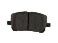
Related Toyota Celica Parts
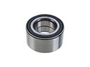 Toyota Celica Wheel Bearing
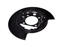 Toyota Celica Backing Plate
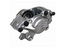 Toyota Celica Brake Caliper
 Toyota Celica Brake Caliper Piston
 Toyota Celica Brake Line
 Toyota Celica Brake Master Cylinder Reservoir
 Toyota Celica Brake Proportioning Valve
 Toyota Celica Brake Rotor
 Toyota Celica Brake Shoe Set
 Toyota Celica Parking Brake Shoes
 Toyota Celica Wheel Cylinder
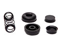 Toyota Celica Wheel Cylinder Repair Kit