×
ToyotaParts- Hello
- Login or Register
- Quick Links
- Live Chat
- Track Order
- Parts Availability
- RMA
- Help Center
- Contact Us
- Shop for
- Toyota Parts
- Scion Parts
My Garage
My Account
Cart
OEM 2009 Toyota Venza Drive Shaft
Axle Shaft- Select Vehicle by Model
- Select Vehicle by VIN
Select Vehicle by Model
orMake
Model
Year
Select Vehicle by VIN
For the most accurate results, select vehicle by your VIN (Vehicle Identification Number).
1 Drive Shaft found

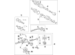
2009 Toyota Venza Drive Shaft
Part Number: 37100-33030$821.27 MSRP: $1203.59You Save: $382.32 (32%)Ships in 1-3 Business DaysProduct Specifications- Other Name: Shaft Assembly, Propeller; Driveshaft; Shaft Assembly, Propeller W/Center Bearing
- Part Name Code: 37100
- Item Weight: 40.40 Pounds
- Item Dimensions: 104.0 x 8.5 x 6.2 inches
- Condition: New
- Fitment Type: Direct Replacement
- SKU: 37100-33030
- Warranty: This genuine part is guaranteed by Toyota's factory warranty.
2009 Toyota Venza Drive Shaft
Looking for affordable OEM 2009 Toyota Venza Drive Shaft? Explore our comprehensive catalogue of genuine 2009 Toyota Venza Drive Shaft. All our parts are covered by the manufacturer's warranty. Plus, our straightforward return policy and speedy delivery service ensure an unparalleled shopping experience. We look forward to your visit!
2009 Toyota Venza Drive Shaft Parts Q&A
- Q: How to remove the drive shaft on 2009 Toyota Venza?A: The first step for removing the drive/propeller shaft is to uninstall the tail exhaust pipe assembly for 1AR-FE or 2GR-FE engines before moving onto the center exhaust pipe assembly for respective engines. First securely depress the brake pedal before using a hexagon wrench (6 mm) to loosen the cross groove joint set bolts by a half-turn but keep them in place. Use either cloth materials or equivalent materials to block the inside section of the universal joint cover to stop boot contact. First indicate the rear propeller shaft and electromagnetic control coupling assembly before removing its 4 nuts and 4 washers. The required tools include a brass bar and hammer to split the propeller with center bearing shaft assembly as well as 4 bolts and 2 No. 1 and 2 No. 2 center support bearing washers which can be extracted by avoiding force application on the universal joint. Extract the propeller with center bearing shaft assembly from the transfer by straightening its universal joint at a 15-degree maximum and treating the oil seal gently. Complete the oil leak prevention using Special Service Tool: 09325-20010 before inserting it into the transfer while ensuring no damage occurs to the oil seal.
Related 2009 Toyota Venza Parts
 2009 Toyota Venza Differential
 2009 Toyota Venza Differential Bearing
 2009 Toyota Venza Drain Plug Washer
 2009 Toyota Venza Harmonic Balancer
 2009 Toyota Venza Pinion Bearing
 2009 Toyota Venza Rod Bearing
 2009 Toyota Venza Timing Chain Tensioner
 2009 Toyota Venza Torque Converter
 2009 Toyota Venza Transfer Case
 2009 Toyota Venza Transfer Case Bearing
 2009 Toyota Venza Transfer Case Seal
 2009 Toyota Venza Valve Stem Seal