×
ToyotaParts- Hello
- Login or Register
- Quick Links
- Live Chat
- Track Order
- Parts Availability
- RMA
- Help Center
- Contact Us
- Shop for
- Toyota Parts
- Scion Parts
My Garage
My Account
Cart
OEM 2009 Toyota Matrix Rear Crossmember
Rear Suspension Crossmember- Select Vehicle by Model
- Select Vehicle by VIN
Select Vehicle by Model
orMake
Model
Year
Select Vehicle by VIN
For the most accurate results, select vehicle by your VIN (Vehicle Identification Number).
2 Rear Crossmembers found

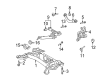 Product Specifications
- Other Name: Member Sub-Assembly, Rear; Suspension Subframe Crossmember, Rear; Member Sub-Assembly, Rear Suspension
- Position: Rear
- Replaces: 51206-12140
- Part Name Code: 51206A
- Item Weight: 38.30 Pounds
- Item Dimensions: 47.5 x 25.1 x 12.3 inches
- Condition: New
- Fitment Type: Direct Replacement
- SKU: 51206-12142
- Warranty: This genuine part is guaranteed by Toyota's factory warranty.

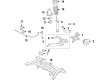 Product Specifications
- Other Name: Member Sub-Assembly, Rear; Suspension Crossmember Bolt; Crossmember; Member Sub-Assembly, Rear Suspension
- Position: Rear
- Part Name Code: 51206A
- Item Weight: 38.30 Pounds
- Item Dimensions: 48.0 x 26.1 x 12.9 inches
- Condition: New
- Fitment Type: Direct Replacement
- SKU: 51206-12150
- Warranty: This genuine part is guaranteed by Toyota's factory warranty.
2009 Toyota Matrix Rear Crossmember
Looking for affordable OEM 2009 Toyota Matrix Rear Crossmember? Explore our comprehensive catalogue of genuine 2009 Toyota Matrix Rear Crossmember. All our parts are covered by the manufacturer's warranty. Plus, our straightforward return policy and speedy delivery service ensure an unparalleled shopping experience. We look forward to your visit!
2009 Toyota Matrix Rear Crossmember Parts Q&A
- Q: How to remove the rear crossmember on 2009 Toyota Matrix?A: The rear cross-member may be removed by the removal of the rear wheels at first. To 2WD, take off the exhaust pipe and charcoal canister; to 4WD, the propeller shaft, drain differential oil also. Disassemble a range of parts, such as brake calipers, speed sensors, and parking brake assemblies, and drop the rear suspension member.
Related 2009 Toyota Matrix Parts
 2009 Toyota Matrix Sway Bar Link
 2009 Toyota Matrix Axle Beam Mount
 2009 Toyota Matrix Bump Stop
 2009 Toyota Matrix Coil Spring Insulator
 2009 Toyota Matrix Coil Springs
 2009 Toyota Matrix Crossmember Bushing
 2009 Toyota Matrix Shock Absorber
 2009 Toyota Matrix Suspension Strut Rod
 2009 Toyota Matrix Sway Bar Bracket
 2009 Toyota Matrix Sway Bar Bushing
 2009 Toyota Matrix Sway Bar Kit
 2009 Toyota Matrix Trailing Arm Bushing