×
ToyotaParts- Hello
- Login or Register
- Quick Links
- Live Chat
- Track Order
- Parts Availability
- RMA
- Help Center
- Contact Us
- Shop for
- Toyota Parts
- Scion Parts
My Garage
My Account
Cart
OEM 2009 Toyota FJ Cruiser Blower Motor
A/C Heater Blower Motor- Select Vehicle by Model
- Select Vehicle by VIN
Select Vehicle by Model
orMake
Model
Year
Select Vehicle by VIN
For the most accurate results, select vehicle by your VIN (Vehicle Identification Number).
1 Blower Motor found


2009 Toyota FJ Cruiser Blower Motor
Part Number: 87103-35100$157.09 MSRP: $222.37You Save: $65.28 (30%)Ships in 1-2 Business DaysProduct Specifications- Other Name: Motor Sub-Assembly, Blower; HVAC Blower Motor Assembly; Blower Assembly; Motor Sub-Assembly, Blower W/Fan; HVAC Blower Motor
- Replaces: 87103-35090
- Part Name Code: 87103B
- Item Weight: 5.80 Pounds
- Item Dimensions: 11.1 x 10.5 x 8.8 inches
- Condition: New
- Fitment Type: Direct Replacement
- SKU: 87103-35100
- Warranty: This genuine part is guaranteed by Toyota's factory warranty.
2009 Toyota FJ Cruiser Blower Motor
Looking for affordable OEM 2009 Toyota FJ Cruiser Blower Motor? Explore our comprehensive catalogue of genuine 2009 Toyota FJ Cruiser Blower Motor. All our parts are covered by the manufacturer's warranty. Plus, our straightforward return policy and speedy delivery service ensure an unparalleled shopping experience. We look forward to your visit!
2009 Toyota FJ Cruiser Blower Motor Parts Q&A
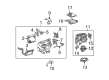
- Q: How to install the Blower Motor assembly and related components on 2009 Toyota FJ Cruiser?A: The installation of the blower unit assembly requires securement using two screws according to the illustrations. Fit the instrument panel reinforcement among other components including the cooler unit drain hose and the instrument panel side bracket and main body ECU (Driver Side J/B). The assembly of steering column and steering intermediate shaft must occur before the installation of the steering column hole cover. Follow the installation order to place the ECM along with the No. 1 instrument panel brace mounting bracket and the three air ducts (No. 1, No. 2, and rear No. 1, No. 2). Then install the heater to register ducts (No. 1, No. 2) and the instrument panel sub-assembly. Then, install the instrument panel sub-assembly, connect the passenger Air Bag connector, and install the instrument panel finish panel end LH, assist grip retainers RH and LH, front No. 2 speaker assembly, No. 2 instrument panel speaker panel sub-assembly, No. 1 instrument panel speaker panel sub-assembly, No. 2 instrument panel register assembly, instrument panel lower finish panel sub-assembly RH, glove compartment door assembly, combination meter assembly, instrument cluster finish panel, lower instrument panel LH, lower instrument panel finish panel sub-assembly LH, instrument panel finish plate, and connect the hood lock control lever sub-assembly. Continue by installing the No. 1 instrument panel register assembly, instrument lower cover sub-assembly, console upper panel No. 1 garnish, front console box, box bottom mat, console upper rear panel sub-assembly, shift lever knob sub-assembly (for Manual Transmission), shift lever knob sub-assembly (for 4WD), parking brake hole cover sub-assembly, radio receiver assembly, integration control and panel assembly, instrument panel garnish LH, instrument panel garnish RH, front pillar garnish RH, front pillar garnish LH, assist grip assembly, assist grip plug, front door opening trim Weather Strip LH, front door opening trim Weather Strip RH, cowl side trim board RH, cowl side trim board LH, footrest clip, front floor footrest, front door scuff plate RH, front door scuff plate LH, combination switch assembly, upper steering column cover, lower steering column cover, steering wheel assembly, steering pad, lower No. 2 steering wheel cover, and lower No. 3 steering wheel cover. The installer must connect the heater water outlet hose A (from heater unit) followed by the heater inlet water hose and then install the cooler refrigerant liquid pipe A and assembly the cooler refrigerant suction pipe A, cowl top ventilator louver LH, cowl top ventilator louver RH along with the cowl top ventilator louver assembly. The installation sequence includes front fender side panel upper LH, front fender side panel upper RH and antenna ornament as well as roof antenna pole sub-assembly alongside front wiper arm and blade assembly LH, front wiper arm and blade assembly RH (center side), front wiper arm and blade assembly RH and windshield wiper arm cover. Engine coolant addition is followed by a 3.9 Nm torque connection of the cable to the negative terminal and a warning light check and refrigerant charging and engine heating before leak detection for coolant and refrigerant. Finally, set the front wheels to face forward.
Related 2009 Toyota FJ Cruiser Parts
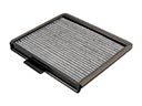 2009 Toyota FJ Cruiser Cabin Air Filter
 2009 Toyota FJ Cruiser A/C Accumulator
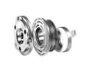 2009 Toyota FJ Cruiser A/C Clutch
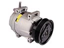 2009 Toyota FJ Cruiser A/C Compressor
 2009 Toyota FJ Cruiser A/C Condenser
 2009 Toyota FJ Cruiser A/C Expansion Valve
 2009 Toyota FJ Cruiser Ambient Temperature Sensor
 2009 Toyota FJ Cruiser Blend Door Actuator
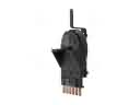 2009 Toyota FJ Cruiser Blower Control Switches
 2009 Toyota FJ Cruiser Blower Motor Resistor
 2009 Toyota FJ Cruiser Evaporator
 2009 Toyota FJ Cruiser Heater Core