×
ToyotaParts- Hello
- Login or Register
- Quick Links
- Live Chat
- Track Order
- Parts Availability
- RMA
- Help Center
- Contact Us
- Shop for
- Toyota Parts
- Scion Parts
My Garage
My Account
Cart
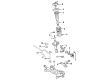
OEM 2008 Toyota Matrix Control Arm
Suspension Arm- Select Vehicle by Model
- Select Vehicle by VIN
Select Vehicle by Model
orMake
Model
Year
Select Vehicle by VIN
For the most accurate results, select vehicle by your VIN (Vehicle Identification Number).
2 Control Arms found


2008 Toyota Matrix Control Arm, Lower Driver Side
Part Number: 48069-02021$186.50 MSRP: $266.29You Save: $79.79 (30%)Ships in 1-3 Business DaysProduct Specifications- Other Name: Arm Sub-Assembly, Suspension; Suspension Control Arm, Front Left; Track Control Arm; Lower Control Arm; Arm Sub-Assembly, Front Suspension, Lower Driver Side; Suspension Control Arm
- Position: Lower Driver Side
- Replaces: 48069-02020
- Part Name Code: 48069
- Item Weight: 1.40 Pounds
- Item Dimensions: 21.6 x 16.3 x 5.7 inches
- Condition: New
- Fitment Type: Direct Replacement
- SKU: 48069-02021
- Warranty: This genuine part is guaranteed by Toyota's factory warranty.

2008 Toyota Matrix Control Arm, Passenger Side
Part Number: 48068-02021$186.50 MSRP: $266.29You Save: $79.79 (30%)Ships in 1-3 Business DaysProduct Specifications- Other Name: Arm Sub-Assembly, Suspension; Suspension Control Arm, Front Right; Track Control Arm; Lower Control Arm; Arm Sub-Assembly, Front Suspension, Lower Passenger Side; Suspension Control Arm
- Position: Passenger Side
- Replaces: 48068-02020
- Part Name Code: 48068
- Item Weight: 12.00 Pounds
- Item Dimensions: 20.4 x 20.1 x 9.4 inches
- Condition: New
- Fitment Type: Direct Replacement
- SKU: 48068-02021
- Warranty: This genuine part is guaranteed by Toyota's factory warranty.
2008 Toyota Matrix Control Arm
Looking for affordable OEM 2008 Toyota Matrix Control Arm? Explore our comprehensive catalogue of genuine 2008 Toyota Matrix Control Arm. All our parts are covered by the manufacturer's warranty. Plus, our straightforward return policy and speedy delivery service ensure an unparalleled shopping experience. We look forward to your visit!
2008 Toyota Matrix Control Arm Parts Q&A
- Q: How to remove the front lower Control Arm on 2008 Toyota Matrix?A: Starting the front lower suspension arm removal requires one to take off the front wheel initially. The removal of front stabilizer link assembly RH begins after disconnecting the LH assembly according to the same steps on the LH side. The front suspension arm sub-assembly lower No. 1 LH unfits from the lower ball joint assembly front LH by bolting out the bolt then unthreading the two nuts. The same procedure must be applied to detach front suspension arm sub-assembly lower No. 1 RH. The rack and pinion power steering gear assembly must be separated through the removal of 4 bolts while carefully loosening the bolt because the nut has limited rotation capability before hanging the assembly. The engineering should then receive suspension treatment. Following the detachment of 3 bolts and 3 nuts the front suspension crossmember sub-assembly can be divided from the transverse engine mounting insulator and engine mounting member sub-assembly center. This sequence needs additional removal of 4 bolts before lowering the transmission jack to extract the front suspension crossmember sub-assembly. Finish the task by unbolting the front suspension arm sub-assembly lower No. 1 LH from the front suspension crossmember sub-assembly using 2 bolts and 1 nut.
Related 2008 Toyota Matrix Parts
 2008 Toyota Matrix Ball Joint
 2008 Toyota Matrix Sway Bar Link
 2008 Toyota Matrix Bump Stop
 2008 Toyota Matrix Coil Spring Insulator
 2008 Toyota Matrix Control Arm Bolt
 2008 Toyota Matrix Front Cross-Member
 2008 Toyota Matrix Shock Absorber
 2008 Toyota Matrix Shock And Strut Mount
 2008 Toyota Matrix Shock and Strut Boot
 2008 Toyota Matrix Steering Knuckle
 2008 Toyota Matrix Strut Housing
 2008 Toyota Matrix Sway Bar Bracket