×
ToyotaParts- Hello
- Login or Register
- Quick Links
- Live Chat
- Track Order
- Parts Availability
- RMA
- Help Center
- Contact Us
- Shop for
- Toyota Parts
- Scion Parts
My Garage
My Account
Cart
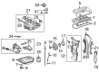
OEM 2008 Scion xB Intake Manifold
Engine Intake Manifold- Select Vehicle by Model
- Select Vehicle by VIN
Select Vehicle by Model
orMake
Model
Year
Select Vehicle by VIN
For the most accurate results, select vehicle by your VIN (Vehicle Identification Number).
1 Intake Manifold found

 Product Specifications
- Other Name: Manifold Assembly, Intake; Engine Intake Manifold; Manifold, Intake
- Manufacturer Note: (L)
- Replaces: 17120-28170, 17120-0H080
- Part Name Code: 17111
- Item Weight: 9.70 Pounds
- Item Dimensions: 18.1 x 13.7 x 7.9 inches
- Condition: New
- Fitment Type: Direct Replacement
- SKU: 17120-0H081
- Warranty: This genuine part is guaranteed by Toyota's factory warranty.
2008 Scion xB Intake Manifold
Looking for affordable OEM 2008 Scion xB Intake Manifold? Explore our comprehensive catalogue of genuine 2008 Scion xB Intake Manifold. All our parts are covered by the manufacturer's warranty. Plus, our straightforward return policy and speedy delivery service ensure an unparalleled shopping experience. We look forward to your visit!
2008 Scion xB Intake Manifold Parts Q&A
- Q: How to remove the intake manifold on 2008 Scion xB?A: The removal process for a 2AZ-FE intake manifold requires as the first step to discharge fuel system pressure. You should begin by taking off the windshield wiper arm cover before moving on to the front wiper arm and blade assembly removal from left and right sides. Proceed by removing the hood to cowl top seal while also taking off the ventilator louvers from both right and left sides of the cowl top. Begin by removing both the front wiper motor along with its link then proceed to remove the outer cowl top panel. The technician must detach three key components: the No. 1 engine cover sub-assembly followed by the air cleaner cap sub-assembly with the No. 1 air cleaner hose after which the throttle body assembly must be separated. The fuel tube sub-assembly requires disconnection which includes taking off the EFI fuel pipe clamp followed by disconnecting the fuel tube. Disassemble the fuel delivery pipe sub-assembly with its fuel tube sub-assembly through injector connector and camshaft oil control valve connector and air fuel ratio sensor connector disconnects and by removing the wire harness and fuel tube sub-assembly. The delivery pipe sub-assembly comes out when you remove the two bolts and then separate the No. 1 delivery pipe spacer and install the four insulators from the cylinder head. Take out the intake manifold by disconnecting the ventilation hose and the union to connector tube hose before removing five bolts along with two nuts followed by the ventilation hose and the bolt for the vacuum hose clamp and then the union to connector tube hose and throttle hose.
Related 2008 Scion xB Parts
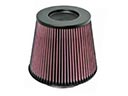 2008 Scion xB Air Filter
 2008 Scion xB Fuel Pump
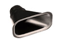 2008 Scion xB Air Duct
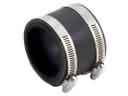 2008 Scion xB Air Intake Coupling
 2008 Scion xB Fuel Filler Neck
 2008 Scion xB Fuel Injector O-Ring
 2008 Scion xB Fuel Level Sensor
 2008 Scion xB Fuel Pressure Regulator
 2008 Scion xB Fuel Pump Seal
 2008 Scion xB Fuel Tank
 2008 Scion xB Intake Manifold Gasket
 2008 Scion xB Throttle Body Gasket