×
ToyotaParts- Hello
- Login or Register
- Quick Links
- Live Chat
- Track Order
- Parts Availability
- RMA
- Help Center
- Contact Us
- Shop for
- Toyota Parts
- Scion Parts
My Garage
My Account
Cart
OEM 2007 Toyota Yaris Sway Bar Kit
Stabilizer Sway Bar Set- Select Vehicle by Model
- Select Vehicle by VIN
Select Vehicle by Model
orMake
Model
Year
Select Vehicle by VIN
For the most accurate results, select vehicle by your VIN (Vehicle Identification Number).
2 Sway Bar Kits found

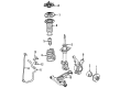
2007 Toyota Yaris Stabilizer Bar, Front
Part Number: 48811-52170$113.04 MSRP: $158.66You Save: $45.62 (29%)Ships in 1-3 Business DaysProduct Specifications- Other Name: Bar, Stabilizer; Suspension Stabilizer Bar, Front; Sway Bar; Bar, Stabilizer, Front
- Position: Front
- Part Name Code: 48811
- Item Weight: 7.50 Pounds
- Item Dimensions: 43.8 x 12.0 x 5.0 inches
- Condition: New
- Fitment Type: Direct Replacement
- SKU: 48811-52170
- Warranty: This genuine part is guaranteed by Toyota's factory warranty.
2007 Toyota Yaris Stabilizer Bar, Front
Part Number: 48811-52160$110.43 MSRP: $155.01You Save: $44.58 (29%)Ships in 1-3 Business DaysProduct Specifications- Other Name: Bar, Stabilizer; Suspension Stabilizer Bar, Front; Sway Bar; Bar, Stabilizer, Front
- Position: Front
- Part Name Code: 48811
- Item Weight: 7.50 Pounds
- Item Dimensions: 43.4 x 12.0 x 5.0 inches
- Condition: New
- Fitment Type: Direct Replacement
- SKU: 48811-52160
- Warranty: This genuine part is guaranteed by Toyota's factory warranty.
2007 Toyota Yaris Sway Bar Kit
Looking for affordable OEM 2007 Toyota Yaris Sway Bar Kit? Explore our comprehensive catalogue of genuine 2007 Toyota Yaris Sway Bar Kit. All our parts are covered by the manufacturer's warranty. Plus, our straightforward return policy and speedy delivery service ensure an unparalleled shopping experience. We look forward to your visit!
2007 Toyota Yaris Sway Bar Kit Parts Q&A
- Q: How to service and repair the front Sway Bar Kit on 2007 Toyota Yaris?A: Start repair and service of the front sway bar kit by disconnecting the negative battery cable then unfastening the hood sub-assembly and front wiper arm head cap and both front wiper arm and blade assemblies (LH and RH). The servicing of hatchback front sway bar kits requires you to take off the hood to cowl top seal and cowl top ventilator louver LH whereas sedan front sway bar kit service demands removal of cowl side ventilator sub-assemblies (LH and RH) and front air shutter seal. The assembly process starts with removal of the cowl top ventilator louver sub-assembly together with the front wiper motor and link and the cowl to register duct sub-assembly (for hatchbacks) followed by the outer cowl top panel. Try positioning the wheels forward while you eliminate the front wheel followed by the column hole cover silencer sheet together with the steering sliding yoke sub-assembly and steering column hole cover sub-assembly. Tie rod end sub-assemblies (LH and RH) should be separated before removing both front lower suspension arms (LH and RH). First suspend the engine assembly then separate the front sway bar link assemblies (LH and RH). Afterward disconnect the front suspension crossmember sub-assembly with power steering gear followed by both front sway bar brackets (LH and RH). Seal the operation by taking out the front sway bar kit and bush. The procedure for inspecting front sway bar link assembly requires five flips of the ball joint stud to install the nut followed by torque wrench measurement on the fifth turn which should be less than 1.0 N m (10 kgf cm, 8.9 in. lbf) alongside dust cover inspection for cracks and grease leakage. Begin with front sway bar bush installation by placing the bush stopper toward the outer side and the cutout in the front vehicle direction. First align the front sway bar kit onto the crossmember with its paint mark on the left side then secure bolt A on the front sway bar bracket LH before completing the tightening between brackets A followed by B to reach 47 N m (479 kgf cm, 35 ft. lbf). Reinstall the front sway bar bracket RH then fit the power steering gear and front suspension crossmember sub-assembly and both front sway bar link assemblies (LH and RH). The processing stage includes front lower suspension arm installation along with tie rod end sub-assemblies and steering column hole cover sub-assembly as well as steering sliding yoke sub-assembly and column hole cover silencer sheet. Reinstall the front wheel by tightening it to 103 N m (1,050 kgf cm, 76 ft. lbf) before putting the wheels in front of each other. Next, reinstall the outer cowl top panel together with the cowl to register duct sub-assembly (for hatchbacks) and the front air shutter seal (for sedans), both the front wiper motor and link and cowl top ventilator louver LH (for hatchbacks), cowl top ventilator louver sub-assembly, hood to cowl top seal (for hatchbacks), and cowl side ventilator sub-assemblies. The service completion includes installing the front wiper blades and wiper arms (LH and RH) along with the front wiper arm head cap before inspecting and adjusting the hood and connecting the battery cable to the negative terminal with 5.4 N m (55 kgf cm, 48 in. lbf) torque and performing front wheel alignment inspection and adjustment.
Related 2007 Toyota Yaris Parts
 2007 Toyota Yaris Control Arm
 2007 Toyota Yaris Sway Bar Link
 2007 Toyota Yaris Alignment Bolt
 2007 Toyota Yaris Bump Stop
 2007 Toyota Yaris Coil Springs
 2007 Toyota Yaris Control Arm Bolt
 2007 Toyota Yaris Shock And Strut Mount
 2007 Toyota Yaris Shock and Strut Boot
 2007 Toyota Yaris Steering Knuckle
 2007 Toyota Yaris Strut Housing
 2007 Toyota Yaris Sway Bar Bracket
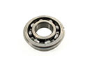 2007 Toyota Yaris Transfer Case Bearing