×
ToyotaParts- Hello
- Login or Register
- Quick Links
- Live Chat
- Track Order
- Parts Availability
- RMA
- Help Center
- Contact Us
- Shop for
- Toyota Parts
- Scion Parts
My Garage
My Account
Cart
OEM 2007 Toyota Yaris Blower Motor
A/C Heater Blower Motor- Select Vehicle by Model
- Select Vehicle by VIN
Select Vehicle by Model
orMake
Model
Year
Select Vehicle by VIN
For the most accurate results, select vehicle by your VIN (Vehicle Identification Number).
1 Blower Motor found


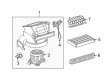
2007 Toyota Yaris Blower Motor
Part Number: 87103-52141$137.35 MSRP: $194.43You Save: $57.08 (30%)Ships in 1-2 Business DaysProduct Specifications- Other Name: Motor Sub-Assembly, Blower; HVAC Blower Motor; Blower Assembly; Motor Sub-Assembly, Blower W/Fan
- Replaces: 87103-52140
- Part Name Code: 87103B
- Item Weight: 3.20 Pounds
- Item Dimensions: 12.5 x 12.4 x 8.2 inches
- Condition: New
- Fitment Type: Direct Replacement
- SKU: 87103-52141
- Warranty: This genuine part is guaranteed by Toyota's factory warranty.
2007 Toyota Yaris Blower Motor
Looking for affordable OEM 2007 Toyota Yaris Blower Motor? Explore our comprehensive catalogue of genuine 2007 Toyota Yaris Blower Motor. All our parts are covered by the manufacturer's warranty. Plus, our straightforward return policy and speedy delivery service ensure an unparalleled shopping experience. We look forward to your visit!
2007 Toyota Yaris Blower Motor Parts Q&A
- Q: How to service the blower motor on 2007 Toyota Yaris?A: Starting the blower motor servicing process demands the removal of the negative battery cable. The right-hand side under cover sub-assembly of the instrument panel needs removal for both Hatchback and Sedan variants. Begin by detaching both the blower motor connector along with clamp before removing its three securing screws. Install the blower motor after positioning it correctly and fastening it with all three screws. Afterwards install the connector then clamp. The instrument panel under cover sub-assembly needs to be reinstalled on the right-hand side for Hatchback and Sedan models before reconnecting the cable to the negative battery terminal with a torque of 5.4 N.m (55 kgf.cm, 48 in.lbf).
Related 2007 Toyota Yaris Parts
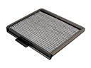 2007 Toyota Yaris Cabin Air Filter
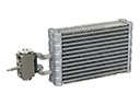 2007 Toyota Yaris Evaporator
 2007 Toyota Yaris A/C Accumulator
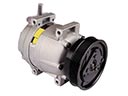 2007 Toyota Yaris A/C Compressor
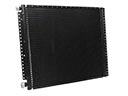 2007 Toyota Yaris A/C Condenser
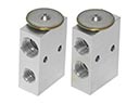 2007 Toyota Yaris A/C Expansion Valve
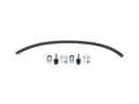 2007 Toyota Yaris A/C Hose
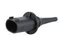 2007 Toyota Yaris Ambient Temperature Sensor
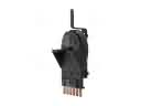 2007 Toyota Yaris Blower Control Switches
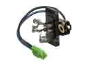 2007 Toyota Yaris Blower Motor Resistor
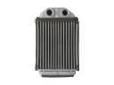 2007 Toyota Yaris Heater Core