×
ToyotaParts- Hello
- Login or Register
- Quick Links
- Live Chat
- Track Order
- Parts Availability
- RMA
- Help Center
- Contact Us
- Shop for
- Toyota Parts
- Scion Parts
My Garage
My Account
Cart
OEM 2007 Toyota Prius Rack And Pinion
Steering Rack And Pinion- Select Vehicle by Model
- Select Vehicle by VIN
Select Vehicle by Model
orMake
Model
Year
Select Vehicle by VIN
For the most accurate results, select vehicle by your VIN (Vehicle Identification Number).
1 Rack And Pinion found

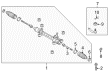
2007 Toyota Prius Steering Gear
Part Number: 45510-47021$761.57 MSRP: $1116.09You Save: $354.52 (32%)Ships in 1-3 Business DaysProduct Specifications- Other Name: Gear Assembly, Steering; Rack and Pinion Assembly; Steering Gearbox; Rack & Pinion; Gear Assembly
- Replaces: 45510-47020
- Part Name Code: 45510
- Item Weight: 12.20 Pounds
- Item Dimensions: 51.2 x 10.7 x 6.6 inches
- Condition: New
- Fitment Type: Direct Replacement
- SKU: 45510-47021
- Warranty: This genuine part is guaranteed by Toyota's factory warranty.
2007 Toyota Prius Rack And Pinion
Looking for affordable OEM 2007 Toyota Prius Rack And Pinion? Explore our comprehensive catalogue of genuine 2007 Toyota Prius Rack And Pinion. All our parts are covered by the manufacturer's warranty. Plus, our straightforward return policy and speedy delivery service ensure an unparalleled shopping experience. We look forward to your visit!
2007 Toyota Prius Rack And Pinion Parts Q&A
- Q: How to service and repair the Rack And Pinion on 2007 Toyota Prius?A: The first step in rack and pinion service and repair requires front wheel alignment toward front while disconnection of negative battery cable for at least 90 seconds to avoid Air Bags and pretensioner activation. First, remove the silencer sheet from the column hole cover before you separate the steering sliding yoke subassembly by fixing the steering wheel with a seat belt to stop rotation and identifying and loosening bolts A and removing bolt B. Then, unfasten No. 1 steering column hole cover by taking off clip A while safeguarding clip B from damage. The front wheel assembly removal process should proceed by removing both No. 2 and No. 1 tie rod ends according to standard procedure. Both front stabilizer link assemblies and front No. 1 stabilizer brackets should be removed by following identical steps for both sides. The technician should position the No. 1 column hole cover at the upper vehicle section and note its location relative to the intermediate shaft and rack and pinion before removing the bolt and cover while safeguarding the clip. Discard the rack and pinion assembly using 4 left-side bolts while being attentive to the stabilizer bar. Both tie rod end sub-assemblies require removal from the rack and pinion assembly that should be fixtured in a vise with SST 09612-00012. Mark the sub-assemblies according to their placement. Use SST 09922-10010 to remove both steering rack boots as well as the end sub-assemblies while maintaining a secure grip of the steering rack. Perform this operation after separating the steering rack boot clips and clamps without causing boot damage. Test the turning torque of both tie rod ends while inspecting the sub-assemblies and change any components exceeding specifications. Using SST 09616-00011 test the total preload of the rack and pinion before conducting necessary replacement of the rack and pinion if needed. The rack and pinion end sub-assemblies need molybdenum disulfide lithium base grease during installation where SST 09922-10010 tools should be used to reach proper torque values. Mount the steering rack boots while keeping them straight and fasten the clamps onto the boots before applying the boot clips. Sales and installation require new rack boot clamps when the rack and pinion assembly demonstrates smooth operation. Fasten the sub-assemblies of tie rod ends with a temporary lock nut installation. Besides protecting the stabilizer bar, install the rack and pinion through the left side and tighten its 4 bolts using 58 Nm (591 kgf-cm, 43 ft. lbs.) torque. The installation of the steering intermediate shaft requires proper placement where the No. 1 column hole cover remains undamaged while using a bolt which should be torqued to 35 Nm (360 kgf-cm, 26 ft. lbs.). Install front stabilizer brackets while linking assemblies to tie rod ends and install front wheels to 103 Nm (1,050 kgf-cm, 76 ft. lbs.). The No. 1 steering column hole cover sub-assembly requires proper fit before sliding the yoke onto the intermediate shaft with both bolts tightened to 35 Nm (360 kgf-cm, 26 ft. lbs.). The last steps require the replacement of the column hole cover silencer sheet followed by checking front wheel straightness and aligning front wheels and calibrating the steering angle sensor while noting that specific systems need initialization post-negative battery terminal reconnection.
Related 2007 Toyota Prius Parts
 2007 Toyota Prius Steering Wheel
 2007 Toyota Prius Steering Angle Sensor
 2007 Toyota Prius Steering Column
 2007 Toyota Prius Steering Shaft
 2007 Toyota Prius Tie Rod End
 2007 Toyota Prius Drag Link
 2007 Toyota Prius Rack and Pinion Boot
 2007 Toyota Prius Steering Column Cover
 2007 Toyota Prius Steering Gear Box
 2007 Toyota Prius Wiper Switch