×
ToyotaParts- Hello
- Login or Register
- Quick Links
- Live Chat
- Track Order
- Parts Availability
- RMA
- Help Center
- Contact Us
- Shop for
- Toyota Parts
- Scion Parts
My Garage
My Account
Cart
OEM 2007 Toyota FJ Cruiser Power Steering Pump
Power Steering Pump Unit- Select Vehicle by Model
- Select Vehicle by VIN
Select Vehicle by Model
orMake
Model
Year
Select Vehicle by VIN
For the most accurate results, select vehicle by your VIN (Vehicle Identification Number).
1 Power Steering Pump found


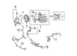
2007 Toyota FJ Cruiser Power Steering Pump
Part Number: 44310-35660$351.38 MSRP: $514.96You Save: $163.58 (32%)Ships in 1-3 Business DaysProduct Specifications- Other Name: Pump Assembly, Vane; Pump
- Replaces: 44310-35650
- Part Name Code: 44310
- Item Weight: 4.10 Pounds
- Item Dimensions: 8.1 x 5.9 x 5.0 inches
- Condition: New
- Fitment Type: Direct Replacement
- SKU: 44310-35660
- Warranty: This genuine part is guaranteed by Toyota's factory warranty.
2007 Toyota FJ Cruiser Power Steering Pump
Looking for affordable OEM 2007 Toyota FJ Cruiser Power Steering Pump? Explore our comprehensive catalogue of genuine 2007 Toyota FJ Cruiser Power Steering Pump. All our parts are covered by the manufacturer's warranty. Plus, our straightforward return policy and speedy delivery service ensure an unparalleled shopping experience. We look forward to your visit!
2007 Toyota FJ Cruiser Power Steering Pump Parts Q&A
- Q: How to service and repair the power steering pump on 2007 Toyota FJ Cruiser?A: Service or repair of the power steering pump starts by disconnecting the negative battery cable followed by the removal of No. 1 engine under cover along with the fan and generator V belt. Perform power steering fluid drainage then remove the No. 1 oil reservoir to pump hose connection by unclipping the retaining mechanism. The pressure feed tube assembly requires union bolt and gasket removal to disconnect it. Start the removal process of the vane pump by disconnecting the oil pressure switch connector then removing the bolt as well as wire harness clamp bracket before removing the two bolts that secure the vane pump assembly. The vane pump assembly goes into a vise using Special Service Tool: 09630-00014 (09631-00132) but avoid extreme tightening of the tool. First, use a combination of bolt and O-ring removal to disconnect the power steering suction port union and then proceed to detach the flow control valve and compression spring by removing the pressure port union with its corresponding O-ring. Quantitative removal starts with the vane pump rear housing four bolts and O-ring then continues with the pulley shaft sub-assembly snap ring removal through screwdriver action and finish with the front side plate O-rings and the vane pump cam ring and plates. A micrometer along with a caliper gauge should be used to check the oil clearance after measuring the vane pump rotor and plates for standard compliance values. Check the functionality of the flow control valve and measure the open length of the compression spring. The vane pump assembly requires complete replacement when any damaged components detect outside standard specifications. You should apply power steering fluid to the noted parts before inserting the pulley shaft sub-assembly through Special Service Tools 09950-60010 (09951-00280) and 09950-70010 (09951-07100) and a press to avoid damaging the oil seal lip. Position the cam ring along with the front side plate after which you should place the vane pump rotor and plates correctly. You should use a new O-ring while installing the rear housing keeping the straight pin in view during the installation process then torque the housing up to 22 N m (224 kgf cm, 16 ft. lbf). Verify the pump preload intensity by allowing a steady movement of the parts while utilizing a recommended special bolt to measure torque values. Secure the power steering oil pressure switch along with the flow control valve and suction port union by using the specified torque values. Proceed with installing the vane pump assembly while reconnecting the pressure feed tube and the No. 1 oil reservoir to pump hose and fan and generator V belt and negative battery terminal. Finish with adding power steering fluid along with bleaching the system before leak inspection and No. 1 engine under cover sub-assembly reinstallation.
Related 2007 Toyota FJ Cruiser Parts
 2007 Toyota FJ Cruiser Drag Link
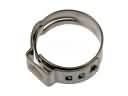 2007 Toyota FJ Cruiser Fuel Line Clamps
 2007 Toyota FJ Cruiser Ignition Switch
 2007 Toyota FJ Cruiser Power Steering Hose
 2007 Toyota FJ Cruiser Power Steering Reservoir
 2007 Toyota FJ Cruiser Rack And Pinion
 2007 Toyota FJ Cruiser Rack and Pinion Boot
 2007 Toyota FJ Cruiser Steering Column Cover
 2007 Toyota FJ Cruiser Steering Gear Box
 2007 Toyota FJ Cruiser Steering Shaft
 2007 Toyota FJ Cruiser Tie Rod End
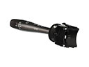 2007 Toyota FJ Cruiser Turn Signal Switch