×
ToyotaParts- Hello
- Login or Register
- Quick Links
- Live Chat
- Track Order
- Parts Availability
- RMA
- Help Center
- Contact Us
- Shop for
- Toyota Parts
- Scion Parts
My Garage
My Account
Cart
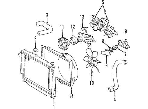
Water Pump
2006 Toyota Tundra Water Pump
Currently shopping for
2006 Toyota Tundra
Change VehicleCategories Close X
Currently selected
Belts & Cooling
Other Categories
A/C & Heating
Air & Fuel Delivery
Body & Hardware
Brakes
Charging & Starting
Driveline & Axles
Electrical
Emission Control & Exhaust
Engine
Headlights & Lighting
Interior & Exterior Trim
Maintenance & Lubrication
Steering
Suspension
Transmission
Categories Close X
How to use OE catalog
4 diagrams found for the vehicle you selected.Select your vehicle options to narrow down results.
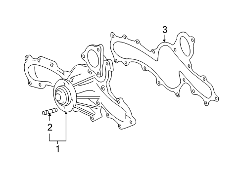
- 1.Cooling - Water Pump (4.0L)
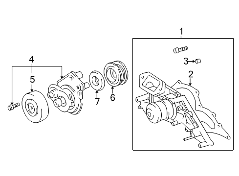
- 2.Cooling - Water Pump (4.7L)
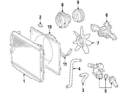
- 3.Cooling System - Water Pump (6 Cyl 4.0 L)
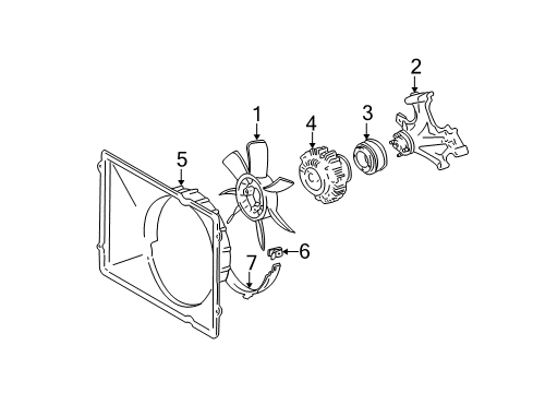
- 4.Cooling System - Water Pump (8 Cyl 4.7 L)
Sort by:
Ref No.
Ref No.
Part No. & Part Description
Price & Qty.
Part No. &
Part Description
Part Description
- 1


 MSRP: $232.20 Your Price: $164.291
 - 1

- 1

- 1
- 1

 MSRP: $202.25 Your Price: $142.871
- 2


 MSRP: $21.44 Your Price: $15.401
- 2

 MSRP: $12.46 Your Price: $8.951
- 2

 MSRP: $2.98 Your Price: $2.141
- 3

 MSRP: $33.75 Your Price: $24.251
 - 3
 MSRP: $40.90 Your Price: $29.391
- 3

 MSRP: $3.48 Your Price: $2.501
- 4


 MSRP: $120.41 Your Price: $85.781
- 4

 MSRP: $53.88 Your Price: $38.711
 - 4
 MSRP: $71.51 Your Price: $51.371
- 5

 MSRP: $157.00 Your Price: $111.851
- 5
 MSRP: $162.71 Your Price: $115.921
- 5
 MSRP: $202.25 Your Price: $142.871
- 6
 MSRP: $12.46 Your Price: $8.951
- 6


 MSRP: $148.35 Your Price: $105.691
- 7
 MSRP: $173.64 Your Price: $122.661
- 7

 MSRP: $7.80 Your Price: $5.60
- 7


 MSRP: $37.91 Your Price: $27.231
- 8


 MSRP: $197.09 Your Price: $139.231
- 8

 MSRP: $8.30 Your Price: $5.961
- 9
 MSRP: $108.77 Your Price: $77.491
- 9

 MSRP: $178.96 Your Price: $126.421
 - 9

 MSRP: $102.11 Your Price: $72.751
- 10

 MSRP: $186.61 Your Price: $131.821
- 10
 MSRP: $184.28 Your Price: $130.181
- 11


 MSRP: $157.00 Your Price: $111.851
- 11


 MSRP: $37.58 Your Price: $27.001
- 12

 MSRP: $111.10 Your Price: $79.151
- 13


 MSRP: $434.11 Your Price: $304.051
- 14
 MSRP: $189.61 Your Price: $133.941
 - 14
 MSRP: $162.49 Your Price: $115.761
")
") MSRP: $1.98 Your Price: $1.42
MSRP: $1.98 Your Price: $1.42
 90341-42001
Plug, Manual Transmission Case- Production Date: 08/2004-12/2006
- Fitting Vehicle Options: GSK30.. 6F
- Part Name Code: 33111A
MSRP: $18.11 Your Price: $13.01

 16100-09470
Pump Assy, Engine Water- Production Date: from 08/2005
- Fitting Vehicle Options: 1GRFE.. GSK30
- Part Name Code: 16100
- Replaced By: 16100-09471
MSRP: $187.61 Your Price: $132.53
")
") MSRP: $2.81 Your Price: $2.02
MSRP: $2.81 Your Price: $2.02
 16100-09200
Pump Assy, Engine Water- Production Date: from 08/2004
- Fitting Vehicle Options: 2UZFE.. UCK3#, 4#
- Part Name Code: 16100
- Replaced By: 16100-09201
MSRP: $202.25 Your Price: $142.87

 16124-31070
Gasket, Water Pump Cover- Part Notes: (J)
- Production Date: from 08/2004
- Fitting Vehicle Options: 1GRFE.. GSK30
- Part Name Code: 16124
- Replaced By: 16124-0P030
MSRP: $18.23 Your Price: $13.10
")
") MSRP: $3.81 Your Price: $2.74
MSRP: $3.81 Your Price: $2.74
") 90253-A0007
90253-A0007
Pin, Ring(For Water Pump Set)- Production Date: from 12/2006
- Fitting Vehicle Options: 2UZFE.. UCK3#, 4#
- Require Quantity: 2
- Package Quantity: 1
- Part Name Code: 11434S
- Replaced By: 90253-11021
MSRP: $3.48 Your Price: $2.50

 MSRP: $2.31 Your Price: $1.66
 16100-39405
Pump Assy, Engine Water- Production Date: 08/2004-08/2005
- Fitting Vehicle Options: 1GRFE.. GSK30
- Part Name Code: 16100
- Replaced By: 16100-09471
MSRP: $187.61 Your Price: $132.53
OEM 2006 Toyota Tundra Parts for Water Pump
Genuine 2006 Toyota Tundra parts are produced by Toyota with the official design and standards, thus they ensure a high quality throughout the production process. OEM parts are the ideal choice for people looking for new Water Pump parts. With our competitive prices, we offer 2006 Toyota Tundra Water Pump that fit tight budgets, while still including the manufacturer warranties, a hassle-free returns policy and quick shipping options.
Water Pump Installation and Repair Tips for 2006 Toyota Tundra
- Q: How to service and repair the water pump on 2006 Toyota Tundra?A: Removing the engine under cover and draining the coolant to service and repair the water pump. Removing fan, generator V belt and radiator reserve tank hose. Disconnect hoses, strip the water inlet and check the water pump on leaks. Change a new gasket and water pump, assemble parts, make sure everything is not leaking and level of coolant.