×
ToyotaParts- Hello
- Login or Register
- Quick Links
- Live Chat
- Track Order
- Parts Availability
- RMA
- Help Center
- Contact Us
- Shop for
- Toyota Parts
- Scion Parts
My Garage
My Account
Cart
OEM 2006 Toyota Sienna Knock Sensor
Engine Knock Sensor- Select Vehicle by Model
- Select Vehicle by VIN
Select Vehicle by Model
orMake
Model
Year
Select Vehicle by VIN
For the most accurate results, select vehicle by your VIN (Vehicle Identification Number).
1 Knock Sensor found


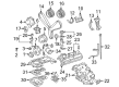
2006 Toyota Sienna Knock Sensor
Part Number: 89615-06010$138.05 MSRP: $195.42You Save: $57.37 (30%)Ships in 1-3 Business DaysProduct Specifications- Other Name: Sensor, Knock Control; Ignition Knock (Detonation) Sensor
- Replaces: 89615-BZ030, 89615-20090, 89615-BZ040
- Part Name Code: 89615
- Item Weight: 0.40 Pounds
- Item Dimensions: 4.1 x 1.9 x 1.4 inches
- Condition: New
- Fitment Type: Direct Replacement
- SKU: 89615-06010
- Warranty: This genuine part is guaranteed by Toyota's factory warranty.
2006 Toyota Sienna Knock Sensor
Looking for affordable OEM 2006 Toyota Sienna Knock Sensor? Explore our comprehensive catalogue of genuine 2006 Toyota Sienna Knock Sensor. All our parts are covered by the manufacturer's warranty. Plus, our straightforward return policy and speedy delivery service ensure an unparalleled shopping experience. We look forward to your visit!
2006 Toyota Sienna Knock Sensor Parts Q&A
- Q: How to remove and install the Knock Sensor on 2006 Toyota Sienna?A: Before uninstalling the Knock Sensor you must discharge fuel system pressure and drain engine coolant. Then, remove the front wiper arm head cap, both front wiper arms (LH and RH), the cowl top ventilator louver sub-assembly, the windshield wiper motor assembly, the No. 1 cowl top to cowl brace inner, the cowl top panel sub-assembly outer front, the V-bank cover sub-assembly, the air cleaner cap sub-assembly, the emission control valve set, the intake air surge tank, and the intake manifold by disconnecting the No. 1 fuel pipe, removing the EFI fuel pipe clamp, pinching the tube connector to pull out the No. 1 fuel pipe, locking the hose clamp, disconnecting the heater water inlet hose B, removing the nut and ground cable, disconnecting the 6 fuel injector connectors, and removing the 9 bolts and 2 nuts in the specified sequence. To extract the engine mounting stay RH you first need to remove its 2 bolts then unplug the radiator hose inlet and radiator reserve tank hose along with the engine coolant temperature sensor connector from the system. Afterward install a new clamp after disassembling the 2 bolts, 2 nuts and 2 washers to remove the water outlet combined with the No. 1 water by-pass hose and take away the 2 cylinder head gaskets. Begin installation of knock sensors by installing their 2 nuts to a 20 N.m torque spec while ensuring a 199 kgf.cm or 14 ft.lbf strength level and then join the 2 knock sensor connectors. You should install 2 new gaskets to the cylinder heads before attaching the water outlet with the No. 1 water by-pass hose while locking the hose clamp. Then tighten the 2 bolts, 2 nuts, and 2 washers to a torque of 15 N.m (153 kgf.cm, 11 ft.lbf). Connect the engine coolant temperature sensor to its connector then attach the radiator reserve tank hose and the radiator hose inlet while installing the clamp. The engine mounting stay RH installation requires a torque value of 23 N.m (235 kgf.cm, 17 ft.lbf) before completing the intake manifold assembly using 9 bolts and 2 nuts which must be tightened in both specified order and sequences and after which the water outlet bolts must be retightened with 15 N.m (153 kgf.cm, 11 ft.lbf) torque. The heater water inlet hose B needs installation together with the No. 1 fuel pipe which needs to have its connector clicked into position before applying the EFI fuel pipe clamp. Install the ground cable with a nut using 8.4 N.m (86 kgf.cm, 74 in.lbf) torque at the end. To finish installation mark the last tasks include fitting the intake air surge tank and adding engine coolant followed by emission control valve set and air cleaner cap sub-assembly while checking for fuel and engine coolant leakage. Finally install the V-bank cover sub-assembly, cowl top panel sub-assembly outer front, No. 1 cowl top to cowl brace inner, windshield wiper motor assembly, cowl top ventilator louver sub-assembly, and both front wiper arms ending with the front wiper arm head cap.
Related 2006 Toyota Sienna Parts
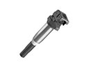 2006 Toyota Sienna Ignition Coil
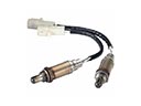 2006 Toyota Sienna Oxygen Sensor
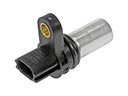 2006 Toyota Sienna Camshaft Position Sensor
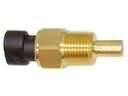 2006 Toyota Sienna Coolant Temperature Sensor
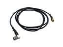 2006 Toyota Sienna Antenna Cable
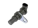 2006 Toyota Sienna Crankshaft Position Sensor
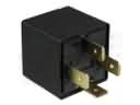 2006 Toyota Sienna Daytime Running Light Relay
 2006 Toyota Sienna Engine Control Module
 2006 Toyota Sienna Headlight Relay
 2006 Toyota Sienna Relay
 2006 Toyota Sienna Relay Block
 2006 Toyota Sienna Spark Plug