×
ToyotaParts- Hello
- Login or Register
- Quick Links
- Live Chat
- Track Order
- Parts Availability
- RMA
- Help Center
- Contact Us
- Shop for
- Toyota Parts
- Scion Parts
My Garage
My Account
Cart
OEM 2006 Toyota Sienna Differential
Front Differential- Select Vehicle by Model
- Select Vehicle by VIN
Select Vehicle by Model
orMake
Model
Year
Select Vehicle by VIN
For the most accurate results, select vehicle by your VIN (Vehicle Identification Number).
2 Differentials found

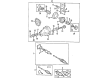
2006 Toyota Sienna Carrier Assembly, Rear
Part Number: 41110-58010$2021.99 MSRP: $2963.25You Save: $941.26 (32%)Ships in 1-3 Business DaysProduct Specifications- Other Name: Carrier Assembly, Differential; Differential Carrier Assembly, Rear; Carrier; Carrier Assembly, Differential, Rear; Differential
- Manufacturer Note: *FGR=41:14=2.928
- Position: Rear
- Part Name Code: 41110
- Item Weight: 78.00 Pounds
- Item Dimensions: 29.9 x 26.6 x 18.0 inches
- Condition: New
- Fitment Type: Direct Replacement
- SKU: 41110-58010
- Warranty: This genuine part is guaranteed by Toyota's factory warranty.


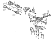
2006 Toyota Sienna Differential Case
Part Number: 41311-14031$291.60 MSRP: $416.34You Save: $124.74 (30%)Product Specifications- Other Name: Case, Differential; Case; Case Sub-Assembly, Rear Differential; Case, Front Differential; Case, Rear Differential; Differential
- Replaces: 41311-14030
- Item Weight: 6.20 Pounds
- Item Dimensions: 6.8 x 6.7 x 6.5 inches
- Condition: New
- Fitment Type: Direct Replacement
- SKU: 41311-14031
- Warranty: This genuine part is guaranteed by Toyota's factory warranty.
2006 Toyota Sienna Differential
Looking for affordable OEM 2006 Toyota Sienna Differential? Explore our comprehensive catalogue of genuine 2006 Toyota Sienna Differential. All our parts are covered by the manufacturer's warranty. Plus, our straightforward return policy and speedy delivery service ensure an unparalleled shopping experience. We look forward to your visit!
2006 Toyota Sienna Differential Parts Q&A
- Q: How to reassemble the rear differential carrier on 2006 Toyota Sienna?A: The reassembly of the rear differential carrier requires insertion of 2 thrust washers onto 2 side gears followed by 2 side gears and 2 differential pinion gears and 2 differential pinion thrust washers and the differential pinion shaft into the differential case while maintaining proper hole alignment. You must inspect the differential pinion gear backlash by inserting the side gear shaft while taking measurements between 0.05 to 0.20 mm (0.0020 to 0.0079 inch); you can reach this specification by using incremental thrust washers of varying thicknesses. Insert a straight pin into the differential case and pinion shaft while using a pin punch before performing stake welding at the pin hole. Apply boiling water to heat the ring gear to 100 degrees Celsius (212 degrees Fahrenheit) while you immediately mount it to the differential case with matchmark alignment. Install 4 new lock plates together with 8 bolts before applying torque to 97 Nm (985 kg-cm, 71 ft-lbs) while staking the lock plates in diagonal order. The rear differential case bearing should be installed with Special Service Tool: 09636-20010 and a press on both RH and LH sides. Dial gauge measurements of the differential ring gear runout with the differential case mounted to the carrier need to show maximum runout values no greater than 0.07 mm (0.0028 inch). Use the Special Service Tool: 09950-60010 (09951-00620) for installation of the rear drive pinion front tapered roller bearing before installing the rear tapered roller bearing with Special Service Tool: 09950-60020 (09951-00710). Follow these steps to adjust differential drive pinion preload using drive pinion along front bearing to torque nut to 108 Nm while providing preload measurements at 1.1 to 1.7 Nm for fresh bearings or 0.6 to 0.9 Nm for replaced bearings. The differential case assembly requires proper installation of bearing outer races which leads to backlash adjustment through right and left bearing cap torque at 79 Nm (800 kg-cm, 58 ft. lbs.) to obtain a 0.13 to 0.18 mm (0.0051 to 0.0071 inch) backlash. Record the combined preload after backlash adjustment because it should fall between 0.3 Nm to 0.5 Nm (3 to 5 kg-cm and 2.6 to 4.3 inch lbs.). Rotate the ring gear while inspecting its contact pattern by applying red lead primer on its surface. Unfasten the rear drive pinion nut, companion flange, then the rear differential drive pinion oil slinger before accessing the front tapered roller bearing. After installing the new bearing spacer the front tapered roller bearing needs to connect to the drive pinion assembly. Use Special Service Tool: 09554-22010 to install the rear differential drive pinion oil slinger andrear differential carrier oil seal with proper depth of 2.0 plus or minus 0.3 mm (0.079 plus or minus 0.012 inches) while applying MP grease to the lip. After installation with Special Service Tool: 09223-00010 of the rear differential dust deflector place the rear drive pinion companion flange sub-assembly while applying hypoid gear oil LSD coated to new nut threads before torquing it to 108 Nm (1,100 kg-cm, 80 ft. lbs.). The drive pinion preload needs measurement for proper values. Adjust the bearing spacer or nut torque if necessary to match the specified values. The last step involves checking the total preload and differential ring gear backlash against specifications while examining the companion flange runout that must not exceed 0.10 mm (0.0039 inch). Follow the process to install 2 new oil seals by using Special Service Tools: 09550-00032, 09950-70010 (09951-07200) and push the oil seal to a depth of 0 plus or minus 0.5 mm (0 plus or minus 0.019 inch) with MP grease application on the lip. Install the rear differential side gear shaft dust cover along with the side gear shaft sub-assembly followed by the rear differential carrier cover according to torque specifications while paying attention to the correct FIPG application before final assembly.
Related 2006 Toyota Sienna Parts
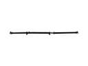 2006 Toyota Sienna Drive Shaft
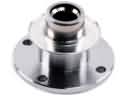 2006 Toyota Sienna CV Joint Companion Flange
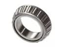 2006 Toyota Sienna Differential Bearing
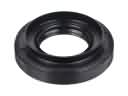 2006 Toyota Sienna Differential Seal
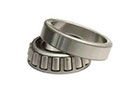 2006 Toyota Sienna Pinion Bearing
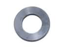 2006 Toyota Sienna Pinion Washer
 2006 Toyota Sienna Transfer Case Bearing
 2006 Toyota Sienna Transfer Case Seal