×
ToyotaParts- Hello
- Login or Register
- Quick Links
- Live Chat
- Track Order
- Parts Availability
- RMA
- Help Center
- Contact Us
- Shop for
- Toyota Parts
- Scion Parts
My Garage
My Account
Cart
OEM 2006 Toyota Highlander Brake Booster
Brake Power Booster- Select Vehicle by Model
- Select Vehicle by VIN
Select Vehicle by Model
orMake
Model
Year
Select Vehicle by VIN
For the most accurate results, select vehicle by your VIN (Vehicle Identification Number).
1 Brake Booster found

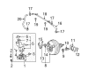
2006 Toyota Highlander Brake Booster
Part Number: 44610-48271$818.21 MSRP: $1199.09You Save: $380.88 (32%)Ships in 1-3 Business DaysProduct Specifications- Other Name: Booster Assembly, Brake; Power Brake Booster; Booster Assembly
- Replaces: 44610-48270
- Item Weight: 8.00 Pounds
- Item Dimensions: 12.6 x 11.7 x 11.1 inches
- Condition: New
- SKU: 44610-48271
- Warranty: This genuine part is guaranteed by Toyota's factory warranty.
2006 Toyota Highlander Brake Booster
Looking for affordable OEM 2006 Toyota Highlander Brake Booster? Explore our comprehensive catalogue of genuine 2006 Toyota Highlander Brake Booster. All our parts are covered by the manufacturer's warranty. Plus, our straightforward return policy and speedy delivery service ensure an unparalleled shopping experience. We look forward to your visit!
2006 Toyota Highlander Brake Booster Parts Q&A
- Q: How to service and repair the vacuum brake booster on 2006 Toyota Highlander?A: Service and repair of the vacuum brake booster needs you to start with removing the front suspension brace sub-assembly upper center before proceeding to pull out the air cleaner assembly for 2AZ-FE or the air cleaner cap filter element and case for 3MZ-FE. First drain the brake fluid then use solution to wipe off paint-contacted fluid droplets before extracting the brake master cylinder assembly and the lower instrument panel finish panel unit. First detach the brake pedal return spring then remove the brake master cylinder push rod clevis after removing its clip and push rod pin and unfastening the push rod lock nut before removing the clevis. The brake tube separation requires the use of Special Service Tool: 09023-00101 to disconnect the clamp's 2 claw fittings while ensuring no brake tube damage occurs. Pull out the brake booster assembly after removing four nuts and discharging it carefully through instrument panel through connector detachment from the check valve assembly by moving the clip backward from the vacuum hose. You must remove the brake booster gasket and complete brake vacuum check valve assembly with its integrated grommet. Evaluate the vacuum check valve after disconnecting the vacuum hose and removing it from position while making sure ventilation functions properly followed by replacement when necessary. Start by inserting the brake booster grommet and check valve assembly into its place in the brake booster assembly followed by applying a new brake booster gasket. Fasten the brake booster assembly using four nuts that need to be tightened at 13 Nm (130 kgf-cm, 9 ft. lbs.), followed by reattaching the vacuum hose. Fitting the 2 clamps of the brake tube to the body must be performed without causing any damage to components. The process involves first mounting the push rod clevis followed by the lock nut then tightening with 26 Nm (265 kgf-cm, 19 ft. lbs.) torque before greasing the clevis pin with lithium soap base glycol and retaining both parts with the push rod pin and clip. Place the brake pedal return spring back into position before you inspect the brake booster push rod for adjustment then install the brake master cylinder sub-assembly. The procedure requires brake fluid filling of the reservoir and subsequent bleeding of the master cylinder and brake line and brake actuator assembly. It also includes reservoir fluid level inspection and brake fluid leakage examination and brake pedal height adjustment. After replacing the lower instrument panel finish panel sub-assembly or the air cleaner assembly for 2AZ-FE or air cleaner case filter element and cap for 3MZ-FE conclude the procedure with the upper center installation of front suspension brace sub-assembly.
Related 2006 Toyota Highlander Parts
 2006 Toyota Highlander ABS Pump And Motor Assembly
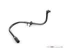 2006 Toyota Highlander Brake Booster Vacuum Hose
 2006 Toyota Highlander Brake Disc
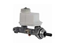 2006 Toyota Highlander Brake Master Cylinder
 2006 Toyota Highlander Brake Master Cylinder Reservoir
 2006 Toyota Highlander Brake Pad Set
 2006 Toyota Highlander Master Cylinder Repair Kit
 2006 Toyota Highlander Wheel Cylinder
 2006 Toyota Highlander Wheel Cylinder Repair Kit
 2006 Toyota Highlander Wheel Hub
 2006 Toyota Highlander Wheel Stud
 2006 Toyota Highlander Yaw Sensor