×
ToyotaParts- Hello
- Login or Register
- Quick Links
- Live Chat
- Track Order
- Parts Availability
- RMA
- Help Center
- Contact Us
- Shop for
- Toyota Parts
- Scion Parts
My Garage
My Account
Cart
OEM 2006 Toyota Avalon Timing Cover
Engine Timing Cover- Select Vehicle by Model
- Select Vehicle by VIN
Select Vehicle by Model
orMake
Model
Year
Select Vehicle by VIN
For the most accurate results, select vehicle by your VIN (Vehicle Identification Number).
1 Timing Cover found

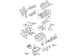
2006 Toyota Avalon Timing Cover, Lower
Part Number: 11310-31020$623.78 MSRP: $914.16You Save: $290.38 (32%)Ships in 1-3 Business DaysProduct Specifications- Other Name: Cover Assembly, Timing Chain Or Belt; Engine Timing Cover, Lower; Front Cover; Lower Timing Cover; Cover Sub-Assembly, Timing Chain Or Belt
- Manufacturer Note: (J)
- Position: Lower
- Replaces: 11310-0P041, 11310-0P040
- Part Name Code: 11302
- Item Weight: 2.40 Pounds
- Item Dimensions: 13.0 x 10.1 x 2.7 inches
- Condition: New
- Fitment Type: Direct Replacement
- SKU: 11310-31020
- Warranty: This genuine part is guaranteed by Toyota's factory warranty.
2006 Toyota Avalon Timing Cover
Looking for affordable OEM 2006 Toyota Avalon Timing Cover? Explore our comprehensive catalogue of genuine 2006 Toyota Avalon Timing Cover. All our parts are covered by the manufacturer's warranty. Plus, our straightforward return policy and speedy delivery service ensure an unparalleled shopping experience. We look forward to your visit!
2006 Toyota Avalon Timing Cover Parts Q&A
- Q: How to Service the Timing Cover on 2006 Toyota Avalon?A: The service process for timing chain or belt cover sub-assembly on 2GR-FE engines requires removal of the engine assembly with transaxle, engine wire, front frame assembly, starter assembly, automatic transaxle assembly, oil level gauge guide sub-assembly, exhaust manifold sub-assemblies (RH and LH), drive plate & ring gear sub-assembly, and idler pulley sub-assembly No.2. After engine wire removal you must take out V-ribbed belt tensioner assembly, water pump pulley, water inlet housing, crankshaft pulley, oil pan sub-assemblies (No.2 and main), oil strainer sub-assembly, intake air surge tank, ignition coil assembly and oil pipes No.1 and No.2. You must then detach both RH and LH cylinder head cover sub-assemblies along with the timing chain or belt cover sub-assembly by undoing 23 bolts and 2 nuts while carefully prying it off to prevent contact surface damage before you remove the gasket. Install the new timing gear case or timing chain case oil seal after separating it from theEquipment with Special Service Tool: 09316-60011 (09316-00011) so the seal edge aligns with the timing chain case and apply MP grease to the lip. The timing chain or belt cover sub-assembly demands application of seal packing (Part No. 08826-00080 or equivalent) into a continuous bead where it contacts both engine unit and timing chain cover. Follow this step by quickly mounting the cover within 3 minutes then securing all bolts within 15 minutes when surfaces remain dry and clean. Before bolt installation begin by fitting a new gasket and position the oil pump drive rotor's spline correctly against the crankshaft followed by loose attachment of the timing chain cover using correct bolts. Then complete torque bolt tightening starting from the first bolt and ending with the last according to torque specifications. Finally, reinstall the cylinder head cover sub-assemblies (LH and RH), oil pipes, ignition coil assembly, intake air surge tank, oil pan sub-assemblies, crankshaft pulley, water inlet housing, water pump pulley, V-ribbed belt tensioner assembly, idler pulley sub-assembly No.2, drive plate & ring gear sub-assembly, exhaust manifold sub-assemblies (LH and RH), oil level gauge guide sub-assembly, automatic transaxle assembly, starter assembly, front frame assembly, engine wire, and the engine assembly with transaxle.
Related 2006 Toyota Avalon Parts
 2006 Toyota Avalon Oil Filter
 2006 Toyota Avalon Cam Gear
 2006 Toyota Avalon Crankshaft Gear
 2006 Toyota Avalon Crankshaft Seal
 2006 Toyota Avalon Dipstick
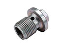 2006 Toyota Avalon Drain Plug
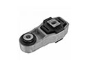 2006 Toyota Avalon Engine Mount Torque Strut
 2006 Toyota Avalon Exhaust Valve
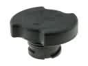 2006 Toyota Avalon Oil Filler Cap
 2006 Toyota Avalon Piston
 2006 Toyota Avalon Timing Chain Tensioner
 2006 Toyota Avalon Variable Timing Sprocket