×
ToyotaParts- Hello
- Login or Register
- Quick Links
- Live Chat
- Track Order
- Parts Availability
- RMA
- Help Center
- Contact Us
- Shop for
- Toyota Parts
- Scion Parts
My Garage
My Account
Cart
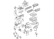
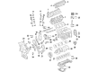
OEM 2006 Toyota 4Runner Timing Cover
Engine Timing Cover- Select Vehicle by Model
- Select Vehicle by VIN
Select Vehicle by Model
orMake
Model
Year
Select Vehicle by VIN
For the most accurate results, select vehicle by your VIN (Vehicle Identification Number).
5 Timing Covers found


2006 Toyota 4Runner Timing Cover, Lower
Part Number: 11302-AC010$55.56 MSRP: $77.32You Save: $21.76 (29%)Ships in 1-3 Business DaysProduct Specifications- Other Name: Cover Sub-Assembly, Timing Chain; Engine Timing Cover, Lower; Cover, Timing Belt
- Manufacturer Note: (L)
- Position: Lower
- Replaced by: 11302-50040
- Part Name Code: 11322A
- Item Weight: 0.50 Pounds
- Item Dimensions: 9.2 x 7.0 x 1.8 inches
- Condition: New
- Fitment Type: Direct Replacement
- SKU: 11302-AC010
- Warranty: This genuine part is guaranteed by Toyota's factory warranty.


2006 Toyota 4Runner Timing Cover, Driver Side
Part Number: 11308-AC010$99.17 MSRP: $139.20You Save: $40.03 (29%)Ships in 1-2 Business DaysProduct Specifications- Other Name: Cover Sub-Assembly, Timing Chain; Engine Timing Cover, Left Upper; Front Cover; Upper Timing Cover; Outer Timing Cover; Cover Sub-Assembly, Timing Belt, Driver Side
- Manufacturer Note: (L)
- Position: Driver Side
- Replaces: 11308-50030
- Part Name Code: 11308C
- Item Weight: 1.40 Pounds
- Item Dimensions: 9.0 x 6.9 x 1.8 inches
- Condition: New
- Fitment Type: Direct Replacement
- SKU: 11308-AC010
- Warranty: This genuine part is guaranteed by Toyota's factory warranty.


2006 Toyota 4Runner Cover Sub-Assembly, Timing Belt, Passenger Side
Part Number: 11304-AC010$101.42 MSRP: $142.37You Save: $40.95 (29%)Ships in 1-3 Business DaysProduct Specifications- Other Name: Cover Sub-Assembly, Timing Chain; Cover, Timing Chain Or Belt; Timing Cover Gasket; Timing Cover Seal; Timing Cover
- Manufacturer Note: (L)
- Position: Passenger Side
- Replaces: 11304-50020
- Item Weight: 1.00 Pounds
- Item Dimensions: 9.4 x 6.9 x 1.7 inches
- Condition: New
- Fitment Type: Direct Replacement
- SKU: 11304-AC010
- Warranty: This genuine part is guaranteed by Toyota's factory warranty.


2006 Toyota 4Runner Timing Cover
Part Number: 11310-31014$703.92 MSRP: $1031.60You Save: $327.68 (32%)Ships in 1-3 Business DaysProduct Specifications- Other Name: Cover Assembly, Timing Chain Or Belt; Engine Timing Cover; Engine Oil Pump; Front Cover
- Replaces: 11310-31013, 11310-0P030
- Item Weight: 19.00 Pounds
- Item Dimensions: 12.8 x 9.7 x 2.7 inches
- Condition: New
- SKU: 11310-31014
- Warranty: This genuine part is guaranteed by Toyota's factory warranty.

2006 Toyota 4Runner Cover Sub-Assembly, Timing Belt, Center Passenger Side
Part Number: 11303-AC010$46.35 MSRP: $64.52You Save: $18.17 (29%)Ships in 1-2 Business DaysProduct Specifications- Other Name: Cover Sub-Assembly, Timing Chain; Timing Cover
- Manufacturer Note: (L)
- Position: Center Passenger Side
- Replaces: 11303-50030
- Part Name Code: 11303B
- Item Weight: 0.80 Pounds
- Item Dimensions: 9.1 x 6.9 x 1.8 inches
- Condition: New
- Fitment Type: Direct Replacement
- SKU: 11303-AC010
- Warranty: This genuine part is guaranteed by Toyota's factory warranty.
2006 Toyota 4Runner Timing Cover
Looking for affordable OEM 2006 Toyota 4Runner Timing Cover? Explore our comprehensive catalogue of genuine 2006 Toyota 4Runner Timing Cover. All our parts are covered by the manufacturer's warranty. Plus, our straightforward return policy and speedy delivery service ensure an unparalleled shopping experience. We look forward to your visit!
2006 Toyota 4Runner Timing Cover Parts Q&A
- Q: How to replace the timing chain or Timing Cover sub-assembly on 2006 Toyota 4Runner?A: Replacement of the timing chain or belt cover sub-assembly begins with removing the power steering link assembly, differential carrier assembly front, draining engine coolant and oil, and removing both the battery and V-bank cover. You must begin by removing 11 clips from the upper radiator support seal then loosen the fan coupling before taking out the fan assembly and V belt of the generator. After disconnecting the ventilation hose No.2 the technician will remove the air cleaner assembly while removing the oil level gauge guide which requires unloading the oil level gauge along with its bolt and O-ring. Remove the water inlet while performing the separation of vane pump assembly then take out the generator assembly and cooler compressor assembly and V-ribbed belt tensioner assembly and the idler pulley sub-assemblies No.1 and No.2. SST 09213-54015 (91651-60855), 09330-00021, 09950-50013 (09951-05010, 09952-05010, 09953-05020, 09954-05030) should be utilized to remove the crankshaft pulley. Subsequently, SST 09032-00100 is used to extract oil pan sub-assembly No.2 before moving on to the oil strainer sub-assembly and oil pan sub-assembly. The technician must discard the intake air surge tank followed by the ignition coil assembly and both cylinder head cover sub-assemblies. Disengage the two oil control valve connectors before you remove the camshaft timing oil control valve assembly and VVT sensor. Take out three bolts and two nuts on the oil filter bracket sub-assembly while removing the sub-assembly for timing chain cover using 24 bolts and two nuts followed by employing careful prying to avoid surface damage before O-ring removal from the LH cylinder head. After wrapping a screwdriver with tape use it to pry the timing chain cover oil seal out. Install New oil seal through SST 09226-10010 and apply a hammer while lubricating the oil seal lip with MP grease. The timing chain cover installation process requires cleaning old packing materials then applying the new O-ring to the LH cylinder head and using Part No. 08826-00080 or equivalent seal packing at specified areas. Align the key way of the oil pump drive rotor to the crankshaft timing gear before placing the timing chain cover on its position and securing it by tightening 24 bolts and two nuts to 23 Nm (235 kgf-cm, 17 ft. lbs.) while verifying the chain and slipper maintain a distance from the seal line. The procedure requires installation of the new gasket between the oil filter bracket sub-assembly and the torque application of three bolts and two nuts to 19 Nm (194 kgf-cm, 14 ft. lbs.) before adding the VVT sensor, camshaft timing oil control valve assembly, and both cylinder head cover sub-assemblies. Correctly install the ignition coil assembly to 10 Nm torque (102 kgf-cm, 7 ft. lbs.) then continue installation with the intake air surge tank and three parts of the oil pan sub-assembly. The crankshaft pulley gets installed using SST 09213-54015 (91651-60855), 09330-00021 while idler pulley sub-assemblies No.1 and No.2, the V-ribbed belt tensioner assembly, cooler compressor assembly, generator assembly, vane pump assembly, water inlet, oil level gauge guide, and air cleaner assembly receive their installation. The ventilation hose No.2 requires attachment and the fan system must be installed with the fluid coupling followed by securing the fan V-belt. Fully tighten the fan using the fluid coupling. You should install the upper radiator support seal before adding the battery as well as the differential carrier assembly front and power steering link assembly. Engine oil and coolant are added before the technician checks for leaks then installs the V-bank cover by tightening two nuts to 7.5 Nm (76 kgf-cm, 66 inch lbs.).
Related 2006 Toyota 4Runner Parts
 2006 Toyota 4Runner Oil Filter
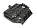 2006 Toyota 4Runner Engine Cover
 2006 Toyota 4Runner Camshaft
 2006 Toyota 4Runner Crankshaft Gear
 2006 Toyota 4Runner Crankshaft Thrust Washer Set
 2006 Toyota 4Runner Cylinder Head Gasket
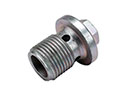 2006 Toyota 4Runner Drain Plug
 2006 Toyota 4Runner Engine Mount
 2006 Toyota 4Runner Intake Valve
 2006 Toyota 4Runner Piston
 2006 Toyota 4Runner Rod Bearing
 2006 Toyota 4Runner Variable Timing Sprocket