×
ToyotaParts- Hello
- Login or Register
- Quick Links
- Live Chat
- Track Order
- Parts Availability
- RMA
- Help Center
- Contact Us
- Shop for
- Toyota Parts
- Scion Parts
My Garage
My Account
Cart
OEM 2006 Scion xB Timing Chain
Engine Timing Chain- Select Vehicle by Model
- Select Vehicle by VIN
Select Vehicle by Model
orMake
Model
Year
Select Vehicle by VIN
For the most accurate results, select vehicle by your VIN (Vehicle Identification Number).
1 Timing Chain found

2006 Scion xB Timing Chain
Part Number: 13506-21050$209.11 MSRP: $298.55You Save: $89.44 (30%)Ships in 1-3 Business DaysProduct Specifications- Other Name: Chain Sub-Assembly, Timing; Chain Sub-Assembly
- Part Name Code: 13506
- Item Weight: 1.20 Pounds
- Item Dimensions: 6.3 x 3.3 x 1.2 inches
- Condition: New
- Fitment Type: Direct Replacement
- SKU: 13506-21050
- Warranty: This genuine part is guaranteed by Toyota's factory warranty.
2006 Scion xB Timing Chain
Looking for affordable OEM 2006 Scion xB Timing Chain? Explore our comprehensive catalogue of genuine 2006 Scion xB Timing Chain. All our parts are covered by the manufacturer's warranty. Plus, our straightforward return policy and speedy delivery service ensure an unparalleled shopping experience. We look forward to your visit!
2006 Scion xB Timing Chain Parts Q&A
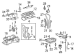
- Q: How to service and repair the timing chain on 2006 Scion xB?A: Before starting service and repair work on the timing chain disconnect the negative battery cable leaving it derouted for minimum ninety seconds to stop Air Bag deployment. The service requires removal of four nuts to access the No. 2 cylinder head cover followed by disassembly of the ignition coils then ventilator hose detachment from the cylinder head cover. After taking off the 9 bolts with two nuts the technician proceeds with removing the generator V belt then the generator followed by the engine under cover RH and draining the engine oil and coolant. Align the timing marks to remove the vane pump V belt, water pump pulley, water pump and crankshaft pulley using Special Service Tools: 09213-58012 (91111-50845), 09330-00021 when removing the pulley bolt. The removal of pulleys can be assisted with Special Service Tool: 09950-50013 (includes 09951-05010, 09952-05010, 09953-05020 and 09954-05021). Unplug the oil control valve connector while removing the bolt which leads to removal of the oil control valve with its O-ring. The crankshaft position sensor along with the engine mounting bracket insulator RH requires removal following engine support with a wooden block. After this, remove the mounting bracket RH. Two bolts must be removed from the timing chain cover and oil pump seal and No.1 chain tensioner. It is important to never rotate the crankshaft when you remove the chain tensioner while making sure the crankshaft faces a 40-degree counterclockwise angle from top dead center during camshaft rotation. Start the chain tensioner slipper removal before taking out the No. 1 chain vibration damper and the chain itself. You must set the No. 1 cylinder to 20 degrees ATDC for the installation process. installation of the chain vibration damper includes two bolts (torque at 9.0 Nm) while maintaining 20 degrees ATDC and placing the timing marks properly before setting the chain tensioner slipper and tensioner (torque at 9.0 Nm). The engine builder must perform a tension check between the sprockets before installing the oil pump seal and timing chain cover as well as water pump and engine mounting bracket RH (torque: 55 Nm) and engine mounting insulator RH (torque: 45 Nm for bolt A, 52 Nm for bolt B and nut). A new O-ring should accompany the camshaft timing oil control valve assembly for installation (torque: 7.5 Nm) together with the crankshaft position sensor and water pump pulley and crankshaft pulley (torque: 128 Nm using Special Service Tool: 09330-00021, 09213-58012 (91111-50845)). Seal packing (Part No. 08826-00080 or equivalent) goes onto the cylinder head cover before installing it with nine bolts using 2 seal washers and 2 nuts where torque is set to 10 Nm. Afterward, connect the No. 2 ventilation hose with the ventilation hose to the cylinder head cover. After installation of the ignition coils (9.0 Nm torque), put on the No. 2 cylinder head cover with 7.0 Nm torque for nuts A and B before adding the generator and vane pump V belt and generator V belt and final belt adjustment. The procedure includes checking drive belt tension along with installation of a new gasket on the oil pan drain plug (torque to 37.5 Nm) followed by engine oil addition and leak inspection and completion with coolant addition and negative battery terminal cable reconnection.
Related 2006 Scion xB Parts
 2006 Scion xB Oil Pan
 2006 Scion xB Cam Gear
 2006 Scion xB Crankshaft Seal
 2006 Scion xB Cylinder Head Gasket
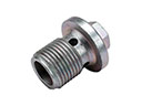 2006 Scion xB Drain Plug
 2006 Scion xB Exhaust Valve
 2006 Scion xB Intake Valve
 2006 Scion xB Oil Filler Cap
 2006 Scion xB Oil Pump
 2006 Scion xB Oil Pump Spring
 2006 Scion xB Piston
 2006 Scion xB Rod Bearing