×
ToyotaParts- Hello
- Login or Register
- Quick Links
- Live Chat
- Track Order
- Parts Availability
- RMA
- Help Center
- Contact Us
- Shop for
- Toyota Parts
- Scion Parts
My Garage
My Account
Cart
OEM 2005 Toyota Prius Rack And Pinion
Steering Rack And Pinion- Select Vehicle by Model
- Select Vehicle by VIN
Select Vehicle by Model
orMake
Model
Year
Select Vehicle by VIN
For the most accurate results, select vehicle by your VIN (Vehicle Identification Number).
1 Rack And Pinion found

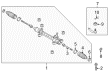
2005 Toyota Prius Steering Gear
Part Number: 45510-47021$761.57 MSRP: $1116.09You Save: $354.52 (32%)Ships in 1-3 Business DaysProduct Specifications- Other Name: Gear Assembly, Steering; Rack and Pinion Assembly; Steering Gearbox; Rack & Pinion; Gear Assembly
- Replaces: 45510-47020
- Part Name Code: 45510
- Item Weight: 12.20 Pounds
- Item Dimensions: 51.2 x 10.7 x 6.6 inches
- Condition: New
- Fitment Type: Direct Replacement
- SKU: 45510-47021
- Warranty: This genuine part is guaranteed by Toyota's factory warranty.
2005 Toyota Prius Rack And Pinion
Looking for affordable OEM 2005 Toyota Prius Rack And Pinion? Explore our comprehensive catalogue of genuine 2005 Toyota Prius Rack And Pinion. All our parts are covered by the manufacturer's warranty. Plus, our straightforward return policy and speedy delivery service ensure an unparalleled shopping experience. We look forward to your visit!
2005 Toyota Prius Rack And Pinion Parts Q&A
- Q: How to overhaul the Rack And Pinion assembly on 2005 Toyota Prius?A: The first step toward rack and pinion assembly replacement requires orientation of the front wheels directly forward. The process to separate the steering sliding yoke sub-assembly starts with fixing the steering wheel assembly with the seat belt in place to stop rotation while marking the sliding yoke sub-assembly and intermediate shaft before loosening bolt A then removing bolt B. First separate the steering column hole cover sub-assembly No.1 by using a tool to remove clip A while protecting clip B. After removing the front wheels, proceed with the tie rod end sub-assembly disconnection followed by the front stabilizer link assembly and both front stabilizer bracket No.1 LH and RH. Start the steering intermediate shaft removal process by moving column hole cover No.1 upwards, making layout marks on the assembly components before removing the bolt. Detach the rack and pinion assembly but avoid hitting the stabilizer bar while removing its four bolts. Hook the rack and pinion assembly inside a vise using Special Service Tool: 09612-00012 with protection tape and disconnect the tie rod end sub-assemblies LH and RH which need alignment markings. Check that the LH tie rod end sub-assembly is proper by first fixing it in a vise while installing the castle nut and checking the ball joint before testing turning torque for replacement when outside specifications. The first step consists of removing steering rack boot clips and clamps to detach the steering rack boots No.1 and No.2. Apply Special Service Tool: 09922-10010 to take off the rack end sub-assemblies from both sides according to the specified direction. The rack and pinion assembly needs replacement by using Special Service Tool: 09616-00011 when the total preload measurement fails to meet specifications. The rack end sub-assemblies should be installed with molybdenum disulfide lithium base grease then torqued to 60 Nm (612 kgf-cm, 44 ft. lbs.). (Position the steering rack boots correctly then fasten them with new clamps while ensuring 3.0 mm (0.12 inch) or less clearance remains between the boot and clamp). Turn the pinion shaft to check whether the rack boots glide smoothly during rack assembly expansion and contraction. Fasten both tie rod end sub-assemblies through the lock nut until their matchmarks reach alignment. The rack and pinion assembly should be installed from the left side between the stabilizer bar while tightening four bolts to 58 Nm (591 kgf-cm, 43 ft. lbs.). Properly position and bolt together the steering intermediate shaft by torquing the bolt to 35 Nm (360 kgf-cm, 26 ft. lbs.). Follow the procedure of installing the front stabilizer brackets then link assembly and tie rod end sub-assemblies before installing and torquing the front wheels to 103 Nm (1,050 kgf-cm, 76 ft. lbs.). Fasten the sub-assembly No.1 of the column hole cover properly and next add the sliding yoke assembly that requires 35 Nm (360 kgf-cm, 26 ft. lbs.) bolt torque. Finalize the process by putting back the column hole cover silencer sheet after checking that the front wheels are straight then adjusting front wheel alignment together with executing steering angle sensor zero point calibration.
Related 2005 Toyota Prius Parts
 2005 Toyota Prius Steering Wheel
 2005 Toyota Prius Steering Angle Sensor
 2005 Toyota Prius Steering Column
 2005 Toyota Prius Steering Shaft
 2005 Toyota Prius Tie Rod End
 2005 Toyota Prius Drag Link
 2005 Toyota Prius Rack and Pinion Boot
 2005 Toyota Prius Steering Column Cover
 2005 Toyota Prius Steering Gear Box
 2005 Toyota Prius Wiper Switch