×
ToyotaParts- Hello
- Login or Register
- Quick Links
- Live Chat
- Track Order
- Parts Availability
- RMA
- Help Center
- Contact Us
- Shop for
- Toyota Parts
- Scion Parts
My Garage
My Account
Cart
OEM 2004 Toyota Prius Rack And Pinion
Steering Rack And Pinion- Select Vehicle by Model
- Select Vehicle by VIN
Select Vehicle by Model
orMake
Model
Year
Select Vehicle by VIN
For the most accurate results, select vehicle by your VIN (Vehicle Identification Number).
1 Rack And Pinion found

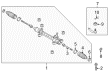
2004 Toyota Prius Steering Gear
Part Number: 45510-47021$761.57 MSRP: $1116.09You Save: $354.52 (32%)Ships in 1-3 Business DaysProduct Specifications- Other Name: Gear Assembly, Steering; Rack and Pinion Assembly; Steering Gearbox; Rack & Pinion; Gear Assembly
- Replaces: 45510-47020
- Part Name Code: 45510
- Item Weight: 12.20 Pounds
- Item Dimensions: 51.2 x 10.7 x 6.6 inches
- Condition: New
- Fitment Type: Direct Replacement
- SKU: 45510-47021
- Warranty: This genuine part is guaranteed by Toyota's factory warranty.
2004 Toyota Prius Rack And Pinion
Looking for affordable OEM 2004 Toyota Prius Rack And Pinion? Explore our comprehensive catalogue of genuine 2004 Toyota Prius Rack And Pinion. All our parts are covered by the manufacturer's warranty. Plus, our straightforward return policy and speedy delivery service ensure an unparalleled shopping experience. We look forward to your visit!
2004 Toyota Prius Rack And Pinion Parts Q&A
- Q: How to overhaul the Rack And Pinion assembly on 2004 Toyota Prius?A: The first step to overhaul the rack and pinion requires proper front wheel alignment towards straight direction. You should remove the column hole silencing sheet from the cover before you separate the sliding yoke sub-assembly by fixing the steering wheel with a seat belt for stability and marking the assembly components. Loosen bolt A first and remove bolt B afterwards. The first step includes detaching the steering column hole cover sub-assembly No.1 while removing clip A gently yet avoiding any damage to clip B. Afterward, extract the front wheels followed by eliminating the left and right tie rod ends and the front stabilizer link assembly and both front stabilizer brackets No.1. To extract the steering intermediate shaft first move up the column hole cover No.1 to release the intermediate shaft. Then perform markings on both components and break the retaining bolt free. After four bolt removal from the rack and pinion assembly keep away from contact with the stabilizer bar. Fasten the rack and pinion assembly to a vise through the use of Special Service Tool: 09612-00012 which requires protection tape covering it. First detach both sub-assemblies of left and right tie rod ends then mark them along with their rack ends before proceeding to remove both sub-assemblies again. The left tie rod end sub-assembly inspection begins by mounting it in a vise and tightening the castle nut then rotating the ball joint while testing turning torque before replacement when out of specification. The inspection procedure should be duplicated for the right tie rod end sub-assembly. Proceed with boot clip and clamp removal from the steering rack while protecting boot integrity and detach both boots. Secure both rack end sub-assemblies using two Special Service Tool: 09922-10010 while maintaining correct directional usage. The inspection requires Special Service Tool: 09616-00011 to check total preload and the rack and pinion assembly must be replaced if it exceeds specifications. Mount the rack end sub-assemblies while filling ball joints with grease and applying torque of 60 Nm (612 kgf-cm, 44 ft. lbs.) using a torque wrench in the correct manner. Both steering rack boots receive silicon grease before their installation and the application of clamps and clips concludes the process while double-checking an absence of boot twists. Check how rack and pinion assembly components move after turning the pinion shaft and inspecting the rack boot functions. The left and right tie rod sub-assemblies should go under installation while the lock nut needs to be tightened temporarily. Install the rack and pinion assembly from the left side while avoiding contact with the stabilizer bar then bolt it to the crossmember with four fasteners at 58 Nm (591 kgf-cm, 43 ft. lbs.). The steering intermediate shaft should be installed with the bolt tightened at 35 Nm (360 kgf-cm, 26 ft. lbs.) while ensuring that hole cover No.1 remains unharmed. Begin installation by placing both front stabilizer brackets followed by installing stabilizer link and final assembly of tie rod end sub-assemblies. Secure the front wheels at 103 Nm (1,050 kgf-cm, 76 ft. lbs.) after which install sub-assembly No.1 of the column hole cover. Proper fitting should be verified. The last step involves aligning the matchmarks to install the sliding yoke sub-assembly while tightening both bolts to 35 Nm (360 kgf-cm, 26 ft. lbs.). Then, reinstall the column hole cover silencer sheet followed by ensuring front wheel straightness. Check and adjust front wheel alignment while performing steering angle sensor zero point calibration.
Related 2004 Toyota Prius Parts
 2004 Toyota Prius Steering Wheel
 2004 Toyota Prius Steering Angle Sensor
 2004 Toyota Prius Steering Column
 2004 Toyota Prius Steering Shaft
 2004 Toyota Prius Tie Rod End
 2004 Toyota Prius Drag Link
 2004 Toyota Prius Rack and Pinion Boot
 2004 Toyota Prius Steering Column Cover
 2004 Toyota Prius Steering Gear Box
 2004 Toyota Prius Wiper Switch