×
ToyotaParts- Hello
- Login or Register
- Quick Links
- Live Chat
- Track Order
- Parts Availability
- RMA
- Help Center
- Contact Us
- Shop for
- Toyota Parts
- Scion Parts
My Garage
My Account
Cart
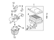
OEM 2005 Toyota Prius Engine Control Module
Engine Control Computer- Select Vehicle by Model
- Select Vehicle by VIN
Select Vehicle by Model
orMake
Model
Year
Select Vehicle by VIN
For the most accurate results, select vehicle by your VIN (Vehicle Identification Number).
1 Engine Control Module found

2005 Toyota Prius ECM
Part Number: 89661-47104$645.80 MSRP: $946.44You Save: $300.64 (32%)Ships in 1-3 Business DaysProduct Specifications- Other Name: Computer, Engine Control; Engine Control Module
- Replaces: 89661-47070, 89661-47103, 89661-47071, 89661-47100, 89661-47101, 89661-47102, 89661-47072
- Item Weight: 1.40 Pounds
- Item Dimensions: 10.1 x 7.5 x 3.3 inches
- Condition: New
- SKU: 89661-47104
- Warranty: This genuine part is guaranteed by Toyota's factory warranty.
2005 Toyota Prius Engine Control Module
Looking for affordable OEM 2005 Toyota Prius Engine Control Module? Explore our comprehensive catalogue of genuine 2005 Toyota Prius Engine Control Module. All our parts are covered by the manufacturer's warranty. Plus, our straightforward return policy and speedy delivery service ensure an unparalleled shopping experience. We look forward to your visit!
2005 Toyota Prius Engine Control Module Parts Q&A
- Q: How to register the Identification Number (VIN) into the replacement Engine Control Module (ECM) on 2005 Toyota Prius?A: A hand-held tester must be used to enter the Vehicle Identification Number (VIN) which contains 17 alphanumeric digits. The registration process demands step-by-step instructions for entering the VIN followed by reading its value before writing it. The tester provides two sets of buttons for input where you can move the cursor with up, down, right, left and use the numerical buttons 0 through 9. The tester controls movement with right and left buttons and accepts alphabetic selections through up and down buttons while each numeric value requires selection using the matching numerical button. Users should navigate to the incorrect character using the right or left buttons to select the correct version of that character after correcting errors during input. The next step after data entry involves verifying the VIN for correctness followed by pushing the enter button to complete the process. The VIN will be accessible through the hand-held tester while using the same method to transfer the VIN to the ECM through the hand-held tester.
Related 2005 Toyota Prius Parts
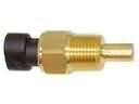 2005 Toyota Prius Coolant Temperature Sensor
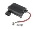 2005 Toyota Prius Fuse Box
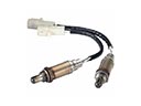 2005 Toyota Prius Oxygen Sensor
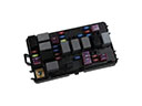 2005 Toyota Prius Fuse
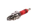 2005 Toyota Prius Spark Plug
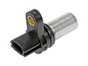 2005 Toyota Prius Camshaft Position Sensor
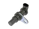 2005 Toyota Prius Crankshaft Position Sensor
 2005 Toyota Prius Daytime Running Light Relay
 2005 Toyota Prius Headlight Relay
 2005 Toyota Prius Knock Sensor
 2005 Toyota Prius Relay
 2005 Toyota Prius Relay Block