×
ToyotaParts- Hello
- Login or Register
- Quick Links
- Live Chat
- Track Order
- Parts Availability
- RMA
- Help Center
- Contact Us
- Shop for
- Toyota Parts
- Scion Parts
My Garage
My Account
Cart
OEM 2005 Toyota MR2 Spyder Rack And Pinion
Steering Rack And Pinion- Select Vehicle by Model
- Select Vehicle by VIN
Select Vehicle by Model
orMake
Model
Year
Select Vehicle by VIN
For the most accurate results, select vehicle by your VIN (Vehicle Identification Number).
2 Rack And Pinions found

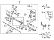 Product Specifications
- Other Name: Gear Assembly, Power Steering; Rack and Pinion Assembly; Steering Gearbox; Gear Assembly; Gear Assembly, Power Steering(For Rack & Pinion)
- Replaces: 44250-17080, 44200-17081
- Part Name Code: 44250
- Item Weight: 17.00 Pounds
- Item Dimensions: 56.0 x 11.7 x 6.8 inches
- Condition: New
- Fitment Type: Direct Replacement
- SKU: 44250-17081
- Warranty: This genuine part is guaranteed by Toyota's factory warranty.
 Product Specifications
- Other Name: Rack Sub-Assembly, Power; Rack And Pinion Rack Gear, Front; Steering Gearbox; Steering Rack; Rack; Rack Sub-Assembly, Power Steering
- Position: Front
- Part Name Code: 44204
- Item Weight: 5.40 Pounds
- Item Dimensions: 32.4 x 3.1 x 2.8 inches
- Condition: New
- Fitment Type: Direct Replacement
- SKU: 44204-17060
- Warranty: This genuine part is guaranteed by Toyota's factory warranty.
2005 Toyota MR2 Spyder Rack And Pinion
Looking for affordable OEM 2005 Toyota MR2 Spyder Rack And Pinion? Explore our comprehensive catalogue of genuine 2005 Toyota MR2 Spyder Rack And Pinion. All our parts are covered by the manufacturer's warranty. Plus, our straightforward return policy and speedy delivery service ensure an unparalleled shopping experience. We look forward to your visit!
2005 Toyota MR2 Spyder Rack And Pinion Parts Q&A
- Q: How to disassemble the Rack And Pinion on 2005 Toyota MR2 Spyder?A: The technician must remove the 2 turn pressure tubes menggunakan SST 09023-38200 while removing the 4 O-rings. SST 09612-00012 should be used to vise the Rack And Pinion assembly. Use a marker to note the positions of tie rod ends and rack ends after which you should loosen the lock nuts while removing the tie rod ends. Use a screwdriver to loosen the clamps before extracted clips, clamps and rack boots from the assembly without harming the boots. The same procedure should be applied to both the LH rack end and RH rack end while using SST 09922-100010 as the tool. Start by using SST 09922-10010 to loosen the rack guide spring cap lock nut followed by removal of the rack guide spring cap together with rack guide spring and rack guide subassembly using a 19 mm hexagon wrench. Use SST 09616-00011 to remove the rack housing cap together with the self-locking nut. Mark the reference points before pulling out the control valve housing assembly with its attached control valve components by removing all bolts. A vinyl tape layer must be wrapped around the control valve shaft before gently pressing out the control valve assembly while taking care to protect the oil seal lip. Use needle nose pliers to remove the snap ring while you extract the cylinder end stopper from the control valve assembly after taking out its oil seal. The rack and pinion should be extracted with bushing using SST 09950-70010 (09951-07200) while removing the O-ring from the bushing. The rack and pinion must have a dial indicator test to check runout levels and teeth wear and damage while maintaining a maximum runout limit of 0.1 mm (0.004 inch). You should use SST 09950-60010 (09951-00210, 09951-00240, 09952-06010) to press out the oil seal from the rack housing and apply power steering fluid on the fresh oil seal lip before installation. Add new oil seal and bearing to the control valve housing by applying SST 09950-60910 (09951-00180, 09951-00330, 09952-06010) along with SST 09950-60010 (09951-00260). The replacement of No.1 and No.2 bearings in the rack housing requires the use of SST 09950-60010 (09951-00220, 09951-00320, 09951-00420, 09951-00430, 09952-06010) together with SST 09950-70010 (09951-07100). Install a new oil seal into the rack and pinion bushing through the use of SST 09612-24814 (09613-22011) while using SST 09950-60010 (09951-00210, 09951-00350, 09952-06010). The teflon ring and O-ring of the rack and pinion should be replaced after ensuring the groove remains undamaged while new teflon rings will be installed into the control valve assembly using SST 09631-20081 for sliding insertion. Strategic Sequence Tool 09631-10041 requires power steering fluid application while the rack receives a coating before insertion into the rack housing. Secure the rack and pinion bushing by installing a new O-ring correctly positioned and pushing in the cylinder end stopper which will be fastened using a snap ring. Use SST 09631-12071 (09633-00010) for air tightness testing and evaluate vacuum resistance. Place the control valve assembly into position while protecting the teflon rings along with oil seal lips and use SST 09612-22011 to press in the oil seal. Initialize the matchmarks to join control valve assembly with control valve housing then fasten it with bolts at 21 Nm (210 kgf-cm, 15 ft. lbs.) and lastly install the dust seal. First apply SST 09616-00010 self-locking nut to a torque of 24.5 Nm (250 kgf-cm, 18 ft. lbs.) then use sealant to treat the rack housing cap threads before the installation to a torque of 59 Nm (600 kgf-cm, 43 ft. lbs.) with subsequent staking. Mount the rack guide sub-assembly and rack guide spring together with the rack guide spring cap on the assembly before finalizing the adjustment of total preload within 0.8 - 1.3 Nm (8 - 13 kgf-cm, 6.9 - 11.3 inch lbs.) after placing rack ends just temporarily. The installation process requires tightening RH and LH rack ends to a proper torque of 62 Nm (630 kgf-cm, 46 ft. lbs.) while installing RH and LH rack boots along with clamps and clips and checking that the rack and pinion end hole is clear before clamping with SST 09521-24010 and finally torquing turn pressure tubes to 10 Nm (100 kgf-cm, 7 ft. lbs.) with new O-rings.
Related 2005 Toyota MR2 Spyder Parts
 2005 Toyota MR2 Spyder Power Steering Pump
 2005 Toyota MR2 Spyder Steering Wheel
 2005 Toyota MR2 Spyder Drag Link
 2005 Toyota MR2 Spyder Ignition Switch
 2005 Toyota MR2 Spyder Power Steering Control Valve
 2005 Toyota MR2 Spyder Power Steering Hose
 2005 Toyota MR2 Spyder Rack and Pinion Boot
 2005 Toyota MR2 Spyder Steering Column Cover
 2005 Toyota MR2 Spyder Steering Gear Box
 2005 Toyota MR2 Spyder Steering Shaft
 2005 Toyota MR2 Spyder Tie Rod End
 2005 Toyota MR2 Spyder Wiper Switch